2810243
SKU
PHX2810243
MPN
MINI MCR-SL-UI-F-SP
Weight
0.111 kg
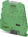
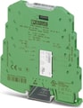
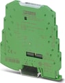
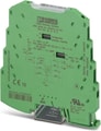
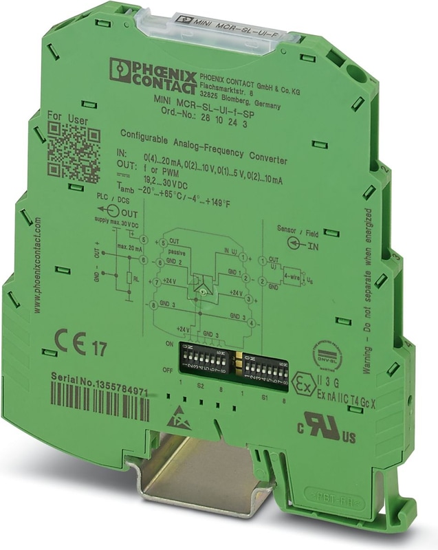
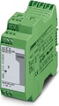
MINI MCR-SL-UI-F-SP - Frequency converter
MCR analog frequency converter for converting standard analog signals into frequency signals or PWM signals, with spring-cage connection. Replacement part: 2902032 MINI MCR-2-UI-FRO-PT.
- Power supply possible via the foot element (TBUS)
- Error indication via diagnostic LED and analog signal
- Highly-compact analog-to-frequency transducer for electrical isolation, amplification, conversion, and filtering of standard signals to create frequencies or PWM signals
- Configurable interference filter
- 3-way isolation
- PWM output of 5 ... 95 %
- Input and output signals can be configured via DIP switches
Technical Specifications
Product properties
| Product family | MINI Analog |
| No. of channels | 1 |
Insulation characteristics
| Overvoltage category | II |
| Pollution degree | 2 |
Electrical properties
| Rated Insulation Voltage | 30 V AC |
| Rated Insulation Voltage | 50 V DC |
| Electrical isolation | Basic insulation in accordance with EN 61010 |
| Electrical isolation between input and output | yes |
| Test voltage, input/output/supply | 1.5 kV AC (50 Hz, 60 s) |
| Step response (0–99%) | < 15 ms (+ (1/f) smallest filter) |
| Step response (0–99%) | < 1 s (+ (1/f) largest filter) |
| Maximum temperature coefficient | < 0.02 %/K |
| Temperature coefficient, typical | < 0.02 %/K |
| Maximum transmission error | ≤ 0.1 % (> 7 kHz ≤ 0.2 %) |
Supply
| Nominal Supply Voltage | 24 V DC |
| Supply Voltage Range | 19.2 V DC ... 30 V DC (The DIN rail connector (ME 6,2 TBUS-2 1,5/5-ST-3,81 GN, item no. 2869728) can be used to bridge the supply voltage. It can be snapped onto a 35 mm DIN rail in accordance with EN 60715) |
| Max. current consumption | < 10 mA (at 24 V DC) |
| Power consumption | < 200 mW |
Signal
| Number of Inputs | 1 |
| Configurable/programmable | Yes |
| Voltage input signal | 0 V ... 5 V |
| Voltage input signal | 1 V ... 5 V |
| Voltage input signal | 0 V ... 10 V |
| Voltage input signal | 2 V ... 10 V |
| Max. voltage input signal | 30 V DC |
| Current Input Signal | 0 mA ... 20 mA |
| Current Input Signal | 4 mA ... 20 mA |
| Current Input Signal | 0 mA ... 10 mA |
| Current Input Signal | 2 mA ... 10 mA |
| Max. current input signal | 100 mA |
| Input resistance of voltage input | approx. 110 kΩ |
| Input resistance current input | approx. 50 Ω |
| Behavior in the event of an error | Alarm in the form of a red LED |
Frequency:
| Frequency output | 0 Hz ... 10 kHz |
| Frequency output | 0 Hz ... 5 kHz |
| Frequency output | 0 Hz ... 2.5 kHz |
| Frequency output | 0 Hz ... 1 kHz |
| Frequency output | 0 Hz ... 500 Hz |
| Frequency output | 0 Hz ... 250 Hz |
| Frequency output | 0 Hz ... 100 Hz |
| Frequency output | 0 Hz ... 50 Hz |
| Load min. | 4 mA ≤ (UL / RL) ≤ 20 mA |
| Output signal PWM | 7.8 kHz (10 bit) |
| Output signal PWM | 3.9 kHz (10 bit) |
| Output signal PWM | 1.9 kHz (12 bit) |
| Output signal PWM | 977 Hz (12 bit) |
| Output signal PWM | 488 Hz (14 bit) |
| Output signal PWM | 244 Hz (14 bit) |
| Output signal PWM | 122 Hz (16 bit) |
| Output signal PWM | 61 Hz (16 bit) |
| Load min. | 12 mA ≤ (UL/RL) ≤ 20 mA |
| Load current maximum | 20 mA |
| Maximum Switching Voltage | 30 V |
| Overrange/underrange | can be set (via DIP switch) |
| Protective circuit | Short-circuit protection, polarity reversal protection |
Signal
| Number of Outputs | 1 |
Connection data
| Connection Method | Spring-cage connection |
| Stripping length | 8 mm |
| Conductor cross section rigid | 0.2 mm² ... 2.5 mm² |
| Conductor cross section flexible | 0.2 mm² ... 2.5 mm² |
| Conductor cross section AWG | 24 ... 12 |
Dimensions
| Width | 6.2 mm |
| Height | 93.1 mm |
| Depth | 102.5 mm |
Material specifications
| Color | green (RAL 6021) |
| Housing Material | PBT |
| Fire protection for rail vehicles (DIN EN 45545-2) R22 | HL 1 - HL 2 |
| Fire protection for rail vehicles (DIN EN 45545-2) R23 | HL 1 - HL 2 |
| Fire protection for rail vehicles (DIN EN 45545-2) R24 | HL 1 - HL 2 |
Ambient conditions
| Degree of Protection | IP20 |
| Ambient Temperature (Operation) | -20 °C ... 65 °C |
| Ambient temperature (storage/transport) | -40 °C ... 85 °C |
| Altitude | ≤ 2000 m |
| Permissible humidity (operation) | 5 % ... 95 % (non-condensing) |
CE
| Certificate | CE-compliant |
ATEX
| Identification | II 3 G Ex nA IIC T4 Gc X |
UL, USA/Canada
| Identification | UL 508 Recognized |
| Identification | Class I, Div. 2, Groups A, B, C, D T4 |
Shipbuilding approval
| Identification | BBBAA |
| Certificate | DNV GL TAA00000N1 |
EMC data
| Noise immunity | EN 61000-6-2 |
| Note | When being exposed to interference, there may be minimal deviations. |
| Electromagnetic compatibility | Conformance with EMC directive |
| Noise emission | EN 61000-6-4 |
Electrostatic discharge
| Standards/regulations | EN 61000-4-2 |
| Comments | Safety measures must be taken to prevent electrostatic discharge. |
Electromagnetic HF field
| Designation | Electromagnetic RF field |
| Standards/regulations | EN 61000-4-3 |
| Typical deviation from the measuring range final value | 2 % |
Fast transients (burst)
| Designation | Fast transients (burst) |
| Standards/regulations | EN 61000-4-4 |
| Typical deviation from the measuring range final value | 2 % |
Surge current load (surge)
| Standards/regulations | EN 61000-4-5 |
| Comments | Criterion B |
Conducted interference
| Designation | Conducted interferences |
| Standards/regulations | EN 61000-4-6 |
| Typical deviation from the measuring range final value | 2 % |
Standards and Regulations
| Electrical isolation | Basic insulation in accordance with EN 61010 |
Mounting
| Mounting Type | DIN rail mounting |
| Mounting Position | any |
Accessories

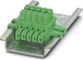 ME 6,2 TBUS-2 1,5/5-ST-3,81 GN - DIN rail connector for DIN rail mounting. Universal for TBUS housing. Gold-plated contacts, 5-pos.
 MINI MCR-SL-PTB-SP - MCR feed-in terminal for supplying several MINI Analog modules via a DIN rail connector, with spring-cage connection, maximum current consumption of up to 2 A. Replacement part: 2902067 MINI MCR-2-PTB-PT.
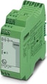 MINI-PS-100-240AC/24DC/1.5/EX - Please use the following item in new systems: 2904614Primary-switched MINI POWER power supply for DIN rail mounting, input: 1-phase, output: 24 V DC/1.5 A, for potentially explosive areas
Why Proax for Phoenix Contact 2810243?
Proax is an authorized distributor of Phoenix Contact 2810243 and one of Phoenix Contact's largest distributors in North America. Our highly skilled in-house technical team is ready to assist with any technical needs.
Have a question in mind? to help you get the right product as quickly as possible for your project. We're always here to help!
Short Lead Time
Highly Trained Staff
Live Chat
Technical Support
Local Inventory
60+ Years Experience
Additional Information
| Pack Size | 1 |
Recommended
 MINI MCR-SL-UI-I-LP-SP-NC, The 6.2 mm wide MINI MCR-SL-UI-I-LP... configurable 2-way isolating amplifier is used to electrically isolate, condition, and filter analog signals.The output loops that supply the loop-powered isolating amplifier enable the isolating amplifier to operate on an active analog input module. The modules are supplied via the current loop of the controller.On the input side, standard analog signals and non-standard analog signals can be connected, starting from 2 mA or 50 mV up to 40 mA or 30 V. These are converted to a 4...20 mA signal.The DIP switches accessible on the housing side enable the configuration of input signal ranges.
 MINI MCR-SL-UI-F - Analog frequency transducers for converting analog standard signals into frequency signals or PWM signals, configurable via DIP switch, with screw connection
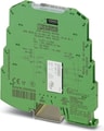 MINI MCR-SL-UI-REL-SP - MCR threshold value switch, with adjustable hysteresis and delay time, with spring-cage connection. Replacement part: 2902035 MINI MCR-2-UI-REL-PT.
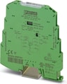 MINI MCR-SL-UI-UI-SP-NC, MCR 3-way isolating amplifier, I/O can be configured via DIP switches, for the electrical isolation of analog signals, with spring-cage connection, standard configuration
 MINI MCR-SL-UI-UI-DUMMY - Non-functioning sample; sample module of a MINI MCR-SL-UI-UI 3-way isolating amplifier.
 MINI MCR-SL-UI-2I, The 6.2 mm wide configurable 4-way isolating amplifier MINI MCR-SL-UI-2I-... is used for electrical isolation, conversion, amplification and filtering of standard signals.On the input side, the analog standard signals 0...20 mA, 4...20 mA, 0...10 V or 1...5V can be selected, on the output side there are two current outputs that can be set independently of one another with a 0...20 mA-, or 4...20mA signal, electrically isolated (4-way isolation).The DIP switches, which can be accessed on the side of the housing, can be used to configure the input and output signal ranges.Power (19.2 V DC to 30 V DC) can be supplied through connection terminal blocks on the modules or in conjunction with the DIN rail connector.
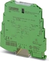 MINI MCR-SL-UI-2I-SP-NC, The 6.2 mm wide configurable 4-way isolating amplifier MINI MCR-SL-UI-2I-... is used for electrical isolation, conversion, amplification and filtering of standard signals.On the input side, the analog standard signals 0...20 mA, 4...20 mA, 0...10 V or 1...5V can be selected, on the output side there are two current outputs that can be set independently of one another with a 0...20 mA-, or 4...20mA signal, electrically isolated (4-way isolation).The DIP switches, which can be accessed on the side of the housing, can be used to configure the input and output signal ranges.Power (19.2 V DC to 30 V DC) can be supplied through connection terminal blocks on the modules or in conjunction with the DIN rail connector.
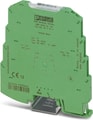 MINI MCR-SL-TB - Feed-through terminal block for transmission of signals that are already electrically isolated
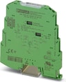 MINI MCR-SL-SHUNT-UI-SP-NC, MCR 3-way isolating amplifier, with configurable input/output, for electrical isolation and conversion of analog signals in the mV range, single-pos. as well as 2-pos. with spring-cage connection, pre-configured
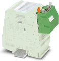 MINI MCR-SL-V8-FLK 16-A, Eight MINI analog signal converters with screw connection method can be connected to a control system using a system adapter and system cabling with a minimum of wiring and very low error risk.
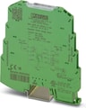 MINI MCR-SL-RPSS-I-I-SP, MCR repeater power supply with HART transmission, input signal 4...20 mA, output signal 4...20 mA, with spring-cage connection.
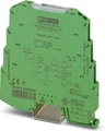 MINI MCR-SL-RPS-I-I-SP, MCR repeater power supplies, spring-cage connection, input signal: (0)4..20 mA, output signal: (0)4..20 mA