2908856
SKU
PHX2908856
MPN
MACX MCR-EX-SL-RPSSI-2I-1S-SP
Weight
0.25 kg
Series MACX-MCR-EX-SL-RPSSI
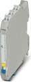
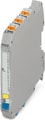
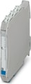
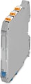
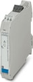
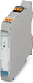
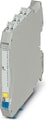
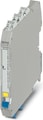
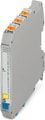
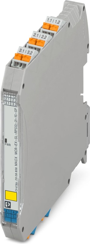
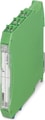
MACX MCR-EX-SL-RPSSI-2I-1S-SP - Repeater power supply
Ex i measuring transducer repeater power supply and input signal conditioner, only output 1 is HART-transparent. Transmits supplied or active electrically isolated signals from the Ex area to two loads. SIL 2 in accordance with IEC 61508, Push-in connection.
Technical Specifications
Utilization restriction
| EMC note | EMC: class A product, see manufacturer's declaration in the download area |
Product properties
| Product family | MACX Analog |
| No. of channels | 1 |
| Type | Ex i signal conditioners with SIL and PL Functional Safety |
Electrical properties
| Electrical isolation between input and output | yes |
| Signal transmission behavior | In = Out |
| Step response (10-90%) | 1.3 ms (Output 1, for jump 4 mA ... 20 mA, typical) |
| Step response (10-90%) | < 100 ms (Output 2, for jump 4 mA ... 20 mA) |
| Maximum temperature coefficient | < 0.01 %/K |
| Maximum transmission error | < 0.1 % (of final value) |
| Transmission error, typical | < 0.05 % (of final value) |
Electrical isolation
| Overvoltage category | II |
| Pollution degree | 2 |
Electrical isolation Input/output/power supply IEC/EN 61010-1
| Standards/regulations | IEC/EN 61010-1 |
| Rated Insulation Voltage | 300 Vrms |
| Test voltage | 2.5 kV AC (50 Hz, 60 s) |
| Insulation | Safe isolation |
Electrical isolation Input/output IEC/EN 60079-11
| Standards/regulations | IEC/EN 60079-11 |
| Rated Insulation Voltage | 265 Vrms |
Electrical isolation Input/power supply IEC/EN 60079-11
| Standards/regulations | IEC/EN 60079-11 |
| Rated Insulation Voltage | 265 Vrms |
Electrical isolation Output 1/output 2
| Test voltage | 1.5 kV AC (50 Hz, 60 s) |
Supply
| Designation | Repeater power supply operation |
| Nominal Supply Voltage | 24 V DC -20 % ... +25 % |
| Supply Voltage Range | 19.2 V DC ... 30 V DC |
| Max. current consumption | < 75 mA (24 V DC / 20 mA) |
| Power dissipation | < 1.45 W (24 V DC / 20 mA) |
| Power consumption | ≤ 1.8 W |
| Designation | Signal conditioner operation |
| Nominal Supply Voltage | 24 V DC -20 % ... +25 % |
| Supply Voltage Range | 19.2 V DC ... 30 V DC |
| Max. current consumption | < 46 mA (24 V DC / 20 mA) |
| Power dissipation | < 1.1 W (24 V DC/20 mA) |
Signal: Repeater power supply operation
| Description of the input | Repeater power supply operation |
| Number of Inputs | 1 |
| Current Input Signal | 4 mA ... 20 mA |
| Transmitter supply voltage | > 16 V (20 mA) |
| Transmitter supply voltage | > 15.1 V (23 mA) |
| Polarization and surge protection | Yes |
| Underload/overload signal range | 0 mA ... 24 mA (Extended transmission range for diagnostics) |
Signal: Signal conditioner operation
| Description of the input | Signal conditioner operation |
| Current Input Signal | 0 mA ... 20 mA |
| Current Input Signal | 4 mA ... 20 mA |
| Voltage drop | approx. 3.9 V (in input isolating amplifier operation) |
| Underload/overload signal range | 0 mA ... 24 mA (Extended transmission range for diagnostics) |
Signal: Repeater power supply operation
| Output description | Repeater power supply operation |
| Number of Outputs | 2 |
| Current Output Signal | 4 mA ... 20 mA (Output 1 and output 2 active) |
| Load/Output Load Current Output | < 450 Ω (20 mA) |
| Load/Output Load Current Output | < 380 Ω (23 mA) |
| Output ripple | < 20 mVrms |
| Output behavior in the event of an error | 0 mA (Cable break in the input) |
| Output behavior in the event of an error | ≥ 23 mA (Cable short-circuit in the input) |
| Underload/overload signal range | 0 mA ... 24 mA (Extended transmission range for diagnostics) |
Signal: Signal conditioner operation
| Output description | Signal conditioner operation |
| Current Output Signal | 0 mA ... 20 mA (active) |
| Current Output Signal | 4 mA ... 20 mA (active) |
| Load/Output Load Current Output | < 450 Ω (20 mA) |
| Load/Output Load Current Output | < 380 Ω (23 mA) |
| Output ripple | < 20 mVrms |
| Output behavior in the event of an error | 0 mA (Cable break in the input) |
| Output behavior in the event of an error | 0 mA (Cable short-circuit in the input) |
| Underload/overload signal range | 0 mA ... 24 mA (Extended transmission range for diagnostics) |
Connection data
| Connection Method | Push-in connection |
| Stripping length | 10 mm |
| Conductor cross section rigid | 0.2 mm² ... 2.5 mm² |
| Conductor cross section flexible | 0.2 mm² ... 2.5 mm² |
| Conductor cross section flexible (2 conductors with same cross section) | 0.25 mm² ... 0.34 mm² (TWIN ferrule without plastic sleeve) |
| Conductor cross section flexible (2 conductors with same cross section) | 0.5 mm² ... 1.5 mm² (TWIN ferrule with plastic sleeve) |
| Conductor cross section AWG | 24 ... 14 |
| Conductor cross section AWG | 24 ... 22 (TWIN ferrule without plastic sleeve) |
| Conductor cross section AWG | 20 ... 16 (TWIN ferrule with plastic sleeve) |
Test socket
| Max. diameter | 2 mm |
Ex data
| Ex installation (EPL) | Gc |
| Ex installation (EPL) | Div. 2 |
| Ex i circuits (EPL) | Ga |
| Ex i circuits (EPL) | Da |
| Ex i circuits (EPL) | Ma |
| Ex i circuits (EPL) | Div. 1 |
Safety data: Repeater power supply operation
| Max. output voltage Uo | 25.2 V |
| Max. output current Io | 93 mA |
| Max. output power Po | 587 mW |
| Safety-related maximum voltage Um | 253 V AC |
| Safety-related maximum voltage Um | 125 V DC |
| I (simple circuit): Max. external inductivity Lo / Max. external capacitance Co | 40 mH / 4.8 µF |
| IIA (simple circuit): Max. external inductivity Lo / Max. external capacitance Co | 26 mH / 2.9 µF |
| IIB (simple circuit): Max. external inductivity Lo / Max. external capacitance Co | 14 mH / 820 nF |
| IIC (simple circuit): Max. external inductivity Lo / Max. external capacitance Co | 3 mH / 107 nF |
| IIA (mixed circuit): Max. external inductivity Lo / Max. external capacitance Co | 26 mH / 470 nF, 20 mH / 570 nF, 1 mH / 630 nF, 0.5 mH / 720 nF, 0.1 mH / 1.1 µF, 0.005 mH / 2.9 µF |
| IIB/IIIC (mixed circuit): Max. external inductivity Lo / Max. external capacitance Co | 16 mH / 370 nF, 1 mH / 430 nF, 500 µH / 510 nF, 200 µH / 660 nF, 100 µH / 820 nF |
| IIC (mixed circuit): Max. external inductivity Lo / Max. external capacitance Co | 2.2 mH / 47 nF, 2 mH / 49 nF, 1 mH / 63 nF, 500 µH / 80 nF, 200 µH / 107 nF |
| I (mixed circuit): Max. external inductivity Lo / Max. external capacitance Co | 37 mH / 0.54 µF, 0.2 mH / 1.1 µF, 10 µH / 2.8 µF, 0.001 mH / 4.15 µF |
Safety data: Signal conditioner operation
| Input voltage Ui | ≤ 30 V |
| Input current Ii | ≤ 150 mA |
| Max. internal inductance Li | negligible |
| Max. internal capacitance Ci | negligible |
| Safety-related maximum voltage Um | 253 V AC |
| Safety-related maximum voltage Um | 125 V DC |
Data communication (bypass)
| HART Function | Yes |
| Protocols Supported | HART-transparent |
| Protocol | HART (only output 1) |
Signaling
| Status display | Green LED (supply voltage) |
Dimensions
| Width | 12.5 mm |
| Height | 107.9 mm |
| Depth | 113.7 mm |
| Depth NS 35/7,5 | 114.5 mm (Snapped onto DIN rail NS 35/7,5 in accordance with EN 60715) |
Material specifications
| Color | gray (RAL 7042) |
| Flammability rating according to UL 94 | V0 (Housing) |
| Housing Material | PA 6.6-FR |
Ambient conditions
| Degree of Protection | IP20 (not assessed by UL) |
| Ambient Temperature (Operation) | -40 °C ... 60 °C (Any mounting position) |
| Ambient Temperature (Operation) | -40 °C ... 70 °C (Derating) |
| Ambient temperature (storage/transport) | -40 °C ... 80 °C |
| Permissible humidity (operation) | 10 % ... 95 % (non-condensing) |
Altitude range (≤ 2000 m)
| Altitude | ≤ 2000 m (The technical data refers to altitudes ≤2000 m above mean sea level. For altitudes >2000 m above mean sea level, refer to the data sheet.) |
| Ambient Temperature (Operation) | -40 °C ... 60 °C |
| Ambient Temperature (Operation) | -40 °C ... 70 °C (Derating) |
| Rated Insulation Voltage | 375 VPP (Power supply, input / output) |
Altitude range (≤ 3000 m)
| Height Range | > 2000 m ... 3000 m |
| Ambient Temperature (Operation) | -40 °C ... 54 °C |
| Ambient Temperature (Operation) | -40 °C ... 63 °C (Derating) |
| Rated Insulation Voltage | 190 V AC (Power supply, input / output) |
| Rated Insulation Voltage | 110 V DC (Power supply, input / output) |
Altitude range (≤ 4000 m)
| Height Range | > 3000 m ... 4000 m |
| Ambient Temperature (Operation) | -40 °C ... 48 °C |
| Ambient Temperature (Operation) | -40 °C ... 56 °C (Derating) |
| Rated Insulation Voltage | 60 V AC/DC (Power supply, input / output) |
Altitude range (≤ 5000 m)
| Height Range | > 4000 m ... 5000 m |
| Ambient Temperature (Operation) | -40 °C ... 42 °C |
| Ambient Temperature (Operation) | -40 °C ... 49 °C (Derating) |
| Rated Insulation Voltage | 60 V AC/DC (Power supply, input / output) |
CE
| Certificate | CE-compliant |
| Note | and EN 61326 |
ATEX
| Identification | II (1) G [Ex ia Ga] IIC |
| Identification | II (1) D [Ex ia Da] IIIC |
| Identification | II 3(1) G Ex ec [ia Ga] IIC T4 Gc |
| Identification | I (M1) [Ex ia Ma] I |
| Certificate | BVS 10 ATEX E 143 X |
IECEx
| Identification | [Ex ia Ga] IIC |
| Identification | [Ex ia Da] IIIC |
| Identification | Ex ec [ia Ga] IIC T4 Gc |
| Identification | [Ex ia Ma] I |
| Certificate | IECEx BVS 10.0097X |
CCC / China-Ex
| Identification | [Ex ia Ga] IIC |
| Identification | [Ex ia Da] IIIC |
| Identification | Ex ec [ia Ga] IIC T4 Gc |
| Certificate | 2022122316115971 |
UL, USA/Canada
| Identification | IS for Class I,II,III, Division 1 and Zone 0 |
| Identification | Installation in Class I, Division 2 and Zone 2 |
| Certificate | , C.D.-No 83104549 |
| Identification | Class I Div 2; IS for Class I, II, III Div 1 |
| Certificate | , C.D.-No 83104549 |
Shipbuilding approval
| Certificate | DNV GL TAA000020C |
Safety Integrity Level (SIL, IEC 61508)
| Identification | 2 |
| Certificate | IN-AT-AS-MRL-23-00432A |
Systematic Capability
| Identification | 3 |
Performance Level (ISO 13849)
| Identification | d / KAT 2 |
INMETRO
| Identification | [Ex ia Ga] IIC |
| Identification | [Ex ia Da] IIIC |
| Identification | Ex ec [ia Ga] IIC T4 Gc |
| Identification | [Ex ia Ma] I |
| Certificate | DNV 18.0139 X |
DNV GL data
| Temperature | B |
| Humidity | B |
| Vibration | A |
| EMC | A |
| Enclosure | Required protection according to the Rules shall be provided upon installation on board |
EMC data
| Noise immunity | EN 61000-6-2 |
| Note | When being exposed to interference, there may be minimal deviations. |
| Electromagnetic compatibility | Conformance with EMC directive |
| Noise emission | EN 61000-6-4 |
GB Standard
| Standards/regulations | GB/T 3836.1 |
| Standards/regulations | GB/T 3836.3 |
| Standards/regulations | GB/T 3836.4 |
Mounting
| Mounting Type | DIN rail mounting |
Accessories

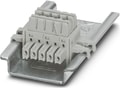 ME 6,2 TBUS-2 1,5/5-ST-3,81 GY - DIN rail connector (TBUS), 5-pos., for bridging the supply voltage, can be snapped onto NS 35/... DIN rail in accordance with EN 60715
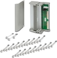 TC-2D37SUB-ADIO32-2EX-P-UNI - Universal Termination Carrier for connecting 16 two-channel MACX Analog Ex i signal conditioners to digital or analog I/O cards, via two D-SUB connectors, 37-pos. (1:1 connection)
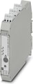 MACX MCR-PTB-SP - Power and fault signaling module with Push-in connection, including corresponding ME 17,5 TBUS 1,5/ 5-ST-3,81 GY DIN rail connector
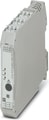
Why Proax for Phoenix Contact 2908856?
Proax is an authorized distributor of Phoenix Contact 2908856 and one of Phoenix Contact's largest distributors in North America. Our highly skilled in-house technical team is ready to assist with any technical needs.
Have a question in mind? to help you get the right product as quickly as possible for your project. We're always here to help!
Short Lead Time
Highly Trained Staff
Live Chat
Technical Support
Local Inventory
60+ Years Experience
Additional Information
| Pack Size | 1 |
Recommended
 MACX MCR-EX-SL-RPSSI-I-DUMMY - Sample without function; sample module of a MACX MCR-EX-SL-RPSSI-I.
 MACX MCR-EX-SL-RTD-I-NC, Ex i temperature measuring transducer: Converts signals from resistance thermometers installed in Ex areas and transmits a 0/4-20 mA signal to a load in the safe area. Freely programmable, 3-way isolation.
 MACX MCR-EX-SL-RTD-I-SP-NC, Ex i temperature measuring transducer: Converts signals from resistance thermometers installed in Ex areas and transmits a 0/4-20 mA signal to a load in the safe area. Freely programmable, 3-way isolation, spring-cage terminal blocks.
 Ex i solenoid driver for controlling Ex i solenoid valves in hazardous areas, logic input, off-load voltage 21.1 V, current limitation at 25.1 mA, line fault transparency, error message output, up to SIL 3 according to IEC 61508; Push-in connection.