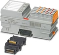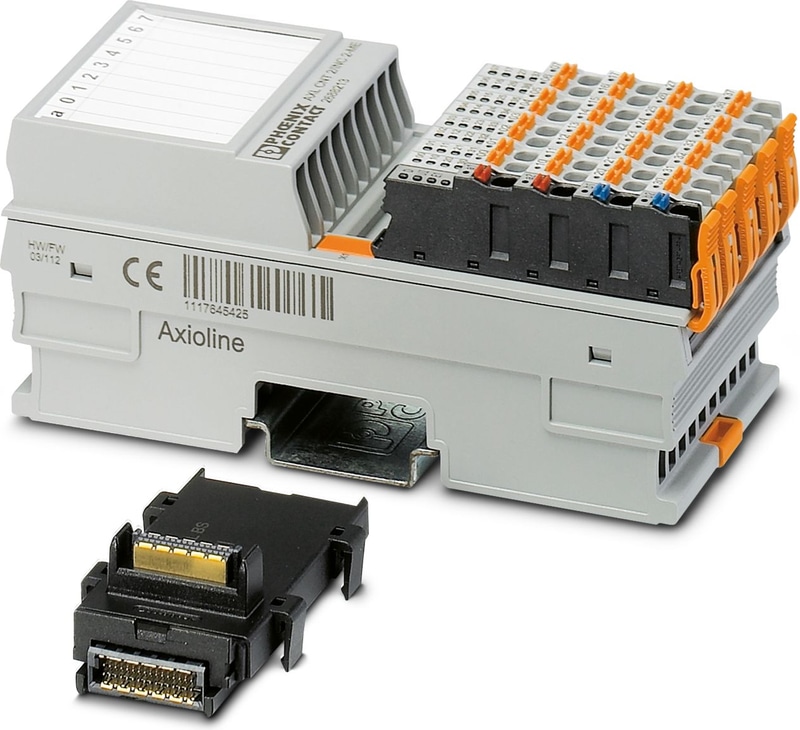
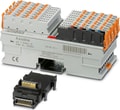
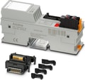
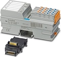
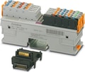
The figure shows the standard item
2701239
SKU
PHX2701239
MPN
AXL F CNT2 INC2 XC 1F
Weight
0.264 kg
This product is Not Cancellable/Not Returnable
Series AXL-F-CNT2
AXL F CNT2 INC2 XC 1F - Function module
Axioline F, Function module, Counter inputs: 2, Incremental encoder inputs: 2, Symmetrical and asymmetrical encoders, Digital inputs: 8, 24 V DC, Digital outputs: 2, 24 V DC, Extreme conditions version, transmission speed in the local bus: 100 Mbps, degree of protection: IP20, including bus base module and Axioline F connectors
- 2 channels, selectable for each channel: counter function or position detection using incremental encoder
- Maximum input frequency: 300 kHz (one channel wired) or 100 kHz (both channels wired)
- 32-bit counter (up and down)
- Output control according to two limit values
- Counter: counting (source) is controlled via a control input (gate)
- Counter: single or periodic counting
- Incremental encoder acquisition: Acquisition of digital signals from symmetrical and asymmetrical incremental encoders
- Incremental encoder acquisition: evaluation of linear or rotary axes
- Device rating plate stored
- Can be used under extreme ambient conditions
- Extended temperature range of -40 °C ... +70 °C (see “Tested successfully: use under extreme ambient conditions” in the data sheet)
- Partially coated PCBs
Technical Specifications
Dimensions
| Width | 53.6 mm |
| Height | 126.1 mm |
| Depth | 54 mm |
| Note on dimensions | The depth applies when a TH 35-7.5 DIN rail is used (in accordance with EN 60715). |
Utilization restriction
| EMC note | EMC: class A product, see manufacturer's declaration in the download area |
Axioline F local bus
| Number of interfaces | 2 |
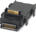
| Connection Method | Bus base module |
| Transmission Speed | 100 Mbps |
Module
| ID code (hex) | none |
| Input address area | 28 Byte |
| Output address area | 28 Byte |
| Required parameter data | 115 Byte |
| Required configuration data | 7 Byte |
Digital:
| Input name | Digital inputs |
| Description of the input | EN 61131-2, type 3 |
| Number of Inputs | 8 (CNT: G1, G2, Dir1, Dir2; INC: Ref1, Ref2, L1, L2) |
| Connection Method | Push-in connection |
| Connection technology | 1-conductor (optional 2, 3-conductor) |
| Input voltage range "0" signal | -3 V DC ... 5 V DC |
| Input voltage range "1" signal | 11 V DC ... 30 V DC |
| Nominal input voltage UIN | 24 V DC |
| Nominal input current at UIN | 2.5 mA (per channel) |
Encoder
| Number of Inputs | 2 (A1, /A1, B1, /B1, Z1, /Z1; A2, /A2, B2, /B2, Z2, /Z2) |
| Input name | Incremental encoder inputs |
| Encoder signals | Symmetrical and asymmetrical encoders |
| Cable Length | max. 30 m |
Counter:
| Input name | Counter inputs |
| Description of the input | EN 61131-2, type 3 |
| Connection Method | Push-in connection |
| Number of Inputs | 2 (S1, S2) |
| Input Voltage | 24 V DC |
| Input voltage range "0" signal | -3 V DC ... 5 V DC |
| Input voltage range "1" signal | 11 V DC ... 30 V DC |
| Input Frequency | max. 300 kHz (1 channel wired) |
| Input Frequency | max. 100 kHz (more than one channel wired or Z signal monitoring via the firmware) |
| Input Current | 2.5 mA (per channel) |
| Resolution | 32 bits |
| Permissible cable length | max. 30 m |
Digital:
| Output name | Digital outputs |
| Connection Method | Push-in connection |
| Connection technology | 1-conductor |
| Number of Outputs | 2 (Out1, Out2) |
| Protective circuit | Short-circuit protection |
| Protective circuit | Overload protection |
| Output Voltage | 24 V DC |
| Maximum Output Current per channel | 500 mA |
| Nominal Output Voltage | 24 V DC |
| Nominal load, inductive | max. 12 VA (1.2 H, 48 Ω, with nominal voltage) |
| Nominal load, lamp | max. 12 W (at nominal voltage) |
| Nominal load, ohmic | max. 12 W (48 Ω, with nominal voltage) |
Product properties
| Product family | Axioline F |
| Type | block modular |
| Mounting Position | any (no temperature derating) |
| Scope of delivery | including bus base module and Axioline F connectors |
| Special Properties | Extreme conditions version |
Insulation characteristics
| Overvoltage category | II (IEC 60664-1, EN 60664-1) |
| Pollution degree | 2 (IEC 60664-1, EN 60664-1) |
Encoder
| Number | 2 (UE1, UE2) |
| Nominal Output Voltage | 5 V DC |
| Voltage range | 5 V DC ... 5.5 V DC |
| Current carrying capacity | max. 250 mA |
| Protective circuit | Short-circuit protection; electronic |
| Number | 2 (US1, US2) |
| Nominal Output Voltage | 24 V DC |
| Voltage range | 19.2 V DC ... 30 V DC |
| Current carrying capacity | typ. 500 mA |
| Protective circuit | Short-circuit protection; electronic |
| Number | max. 2 (A, /A, B, /B, (Z, /Z)) |
| Designation | Symmetrical incremental encoders |
| Type of connection of signals | Push-in connection |
| Encoder supply voltage | 5 V DC |
| Encoder supply voltage | 24 V DC |
| Signal voltage level | Differential signal (signal – inverted signal) ±0.5 V, minimum; ±6 V, maximum |
| Common mode voltage range signal - ground | -10 V ... 13.2 V |
| Input Frequency | max. 300 kHz (1 channel wired) |
| Input Frequency | max. 100 kHz (more than one channel wired or Z signal monitoring via the firmware) |
| Number | max. 2 (A, B, (Z)) |
| Designation | Asymmetrical incremental encoder |
| Type of connection of signals | Push-in connection |
| Signal voltage level | Low ≤ 2.5 V, high ≥ 3.5 V (up to 27 V, maximum) |
| Input Frequency | max. 300 kHz (1 channel wired) |
| Input Frequency | max. 100 kHz (more than one channel wired or Z signal monitoring via the firmware) |
Potentials: Axioline F local bus supply (UBus)
| Supply Voltage | 5 V DC (via bus base module) |
| Current draw | max. 120 mA |
| Current draw | typ. 100 mA |
| Power consumption | max. 0.6 W |
| Power consumption | typ. 0.5 W |
Potentials: Feed-in of supply voltage (UI)
| Supply Voltage | 24 V DC |
| Supply Voltage Range | 19.2 V DC ... 30 V DC (including all tolerances, including ripple) |
| Current draw | max. 2.5 A (dependent on the encoder or sensor type used and the load on the digital output.) |
| Power consumption | max. 60 W (of which 1.6 W internal losses) |
| Protective circuit | Surge protection; electronic (35 V, 0.5 s) |
| Protective circuit | Reverse polarity protection; parallel diode; with external 5 A fuse (only for commissioning) |
Electrical isolation/isolation of the voltage ranges
| Test voltage: 5 V supply of the local bus (UBus) / 24 V supply (I/Os) | 500 V AC, 50 Hz, 1 min. |
| Test voltage: 5 V supply of the local bus (UBus) / functional ground | 500 V AC, 50 Hz, 1 min. |
| Test voltage: 24 V supply (I/O) / functional ground | 500 V AC, 50 Hz, 1 min. |
Connection technology
| Connection name | Axioline F connector |
| Note on the connection method | Please observe the information provided on conductor cross sections in the “Axioline F: system and installation” user manual. |
Conductor connection
| Connection Method | Push-in connection |
| Conductor cross section rigid | 0.2 mm² ... 1.5 mm² |
| Conductor cross section flexible | 0.2 mm² ... 1.5 mm² |
| Conductor cross section AWG | 24 ... 16 |
| Stripping length | 8 mm |
Axioline F connector
| Connection Method | Push-in connection |
| Note on the connection method | Please observe the information provided on conductor cross sections in the “Axioline F: system and installation” user manual. |
| Conductor cross section, rigid | 0.2 mm² ... 1.5 mm² |
| Conductor cross section, flexible | 0.2 mm² ... 1.5 mm² |
| Conductor cross section AWG | 24 ... 16 |
| Stripping length | 8 mm |
Ambient conditions
| Ambient Temperature (Operation) | -25 °C ... 60 °C (Standard, applications with UL approval, use in zone 2 potentially explosive area) |
| Ambient Temperature (Operation) | -40 °C ... 70 °C (Extended, see section “Tested successfully: use under extreme ambient conditions” in the data sheet.) |
| Degree of Protection | IP20 |
| Air pressure (operation) | 70 kPa ... 106 kPa (up to 3000 m above sea level) |
| Air pressure (storage/transport) | 70 kPa ... 106 kPa (up to 3000 m above sea level) |
| Ambient temperature (storage/transport) | -40 °C ... 85 °C |
| Permissible humidity (operation) | 5 % ... 95 % (non-condensing) |
| Permissible humidity (storage/transport) | 5 % ... 95 % (non-condensing) |
Standards and Regulations
| Protection class | III (IEC 61140, EN 61140, VDE 0140-1) |
ATEX
| Identification | II 3 G Ex ec IIC T4 Gc |
| Certificate | UL 20 ATEX 2441X |
| References to standards | EN IEC 60079-0, EN IEC 60079-7 |
UKEX
| Identification | II 3 G Ex ec IIC T4 Gc |
| Certificate | PxCIMA22UKEX2701949X |
| References to standards | EN IEC 60079-0, EN IEC 60079-7 |
IECEx
| Identification | Ex ec IIC T4 Gc |
| Certificate | IECEx ULD 20.0026X |
| References to standards | IEC 60079-0 Ed. 7, IEC 60079-7 Ed. 5.1 |
UL, USA/Canada
| Identification | cULus |
| Certificate | E238705 |
UL Ex, USA / Canada
| Identification | Class I, Zone 2, AEx ec IIC T4 |
| Identification | Class I, Division 2, Groups A, B, C, D, T4 |
| Identification | Ex ec IIC T4 Gc X |
| Certificate | E366272 |
| References to standards | UL 60079-0 Ed. 7 / CSA C22.2 NO. 60079-0 Ed. 4 |
| References to standards | UL 60079-7 Ed. 5 / CSA C22.2 NO. 60079-7 Ed. 2 |
CCC / China-Ex
| Identification | Ex ec IIC T4 Gc |
| Certificate | , 2021122309114456 |
| References to standards | GB/T 3836.1-2021, GB/T 3836.3-2021 |
Mounting
| Mounting Type | DIN rail mounting |
| Mounting Position | any (no temperature derating) |
Accessories


Why Proax for Phoenix Contact 2701239?
Proax is an authorized distributor of Phoenix Contact 2701239 and one of Phoenix Contact's largest distributors in North America. Our highly skilled in-house technical team is ready to assist with any technical needs.
Have a question in mind? to help you get the right product as quickly as possible for your project. We're always here to help!
Short Lead Time
Highly Trained Staff
Live Chat
Technical Support
Local Inventory
60+ Years Experience
Additional Information
| Pack Size | 1 |
Recommended

 AXL F CNT2 INC2 1F - Axioline F, Function module, Counter inputs: 2, Incremental encoder inputs: 2, Symmetrical and asymmetrical encoders, Digital inputs: 8, 24 V DC, Digital outputs: 2, 24 V DC, transmission speed in the local bus: 100 Mbps, degree of protection: IP20, including bus base module and Axioline F connectors
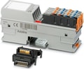 AXL F DO8/2 2A 1H - Axioline F, Digital output module, Digital outputs: 8, 24 V DC, 2 A, connection technology: 2-conductor, transmission speed in the local bus: 100 Mbps, degree of protection: IP20, including bus base module and Axioline F connectors
- AXL F DO8/2 2A XC 1H - Axioline F, Digital output module, Digital outputs: 8, 24 V DC, 2 A, connection technology: 2-conductor, Extreme conditions version, transmission speed in the local bus: 100 Mbps, degree of protection: IP20, including bus base module and Axioline F connectors
 AXL F DO64/1 2F - Axioline F, Digital output module, Digital outputs: 64, 24 V DC, 500 mA, connection technology: 1-conductor, transmission speed in the local bus: 100 Mbps, degree of protection: IP20, including bus base module and Axioline F connectors
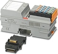 Axioline F, Digital output module, Digital outputs: 4 (Triac outputs with zero voltage switch), 230 V AC, 2 A, connection technology: 3-conductor, transmission speed in the local bus: 100 Mbps, degree of protection: IP20, including bus base module and Axioline F connectors
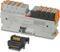 AXL F DO32/1 2H - Axioline F, Digital output module, Digital outputs: 32, 24 V DC, 500 mA, connection technology: 1-conductor, transmission speed in the local bus: 100 Mbps, degree of protection: IP20, including bus base module and Axioline F connectors
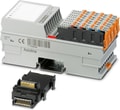 AXL F DO32/1 1F - Axioline F, Digital output module, Digital outputs: 32, 24 V DC, 500 mA, connection technology: 1-conductor, transmission speed in the local bus: 100 Mbps, degree of protection: IP20, including bus base module and Axioline F connectors
- AXL F DO32/1 XC 1F - Axioline F, Digital output module, Digital outputs: 32, 24 V DC, 500 mA, connection technology: 1-conductor, Extreme conditions version, transmission speed in the local bus: 100 Mbps, degree of protection: IP20, including bus base module and Axioline F connectors
 AXL F DO16 FLK 1H - Axioline F, Digital output module, Digital outputs: 16, 24 V DC, 500 mA, connection technology: FLK connector (20-pos.), transmission speed in the local bus: 100 Mbps, degree of protection: IP20, including bus base module and Axioline F connector
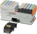 AXL F DO16/3 2F - Axioline F, Digital output module, Digital outputs: 16, 24 V DC, 500 mA, connection technology: 3-conductor, transmission speed in the local bus: 100 Mbps, degree of protection: IP20, including bus base module and Axioline F connectors
- AXL F DO16/3 XC 2F - Axioline F, Digital output module, Digital outputs: 16, 24 V DC, 500 mA, connection technology: 3-conductor, Extreme conditions version, transmission speed in the local bus: 100 Mbps, degree of protection: IP20, including bus base module and Axioline F connectors
 AXL F DO16/2 2H - Axioline F, Digital output module, Digital outputs: 16, 24 V DC, 500 mA, connection technology: 2-conductor, transmission speed in the local bus: 100 Mbps, degree of protection: IP20, including bus base module and Axioline F connectors
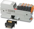 AXL F DO16/1 1H - Axioline F, Digital output module, Digital outputs: 16, 24 V DC, 500 mA, connection technology: 1-conductor, transmission speed in the local bus: 100 Mbps, degree of protection: IP20, including bus base module and Axioline F connectors
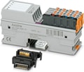 AXL F DI8/1 DO8/1 1H - Axioline F, Digital I/O module, Digital inputs: 8, 24 V DC, connection technology: 1-conductor, Digital outputs: 8, 24 V DC, 500 mA, connection technology: 1-conductor, transmission speed in the local bus: 100 Mbps, degree of protection: IP20, including bus base module and Axioline F connectors
- AXL F DI8/1 DO8/1 XC 1H - Axioline F, Digital I/O module, Digital inputs: 8, 24 V DC, connection technology: 1-conductor, Digital outputs: 8, 24 V DC, 500 mA, connection technology: 1-conductor, Extreme conditions version, transmission speed in the local bus: 100 Mbps, degree of protection: IP20, including bus base module and Axioline F connectors
 AXL F DI8/2 48/60DC 1F - Axioline F, Digital input module, Digital inputs: 8, 48 V DC / 60 V DC, connection technology: 2-conductor, corresponds to standard IEC 61850-3, transmission speed in the local bus: 100 Mbps, degree of protection: IP20, including bus base module and Axioline F connectors
- AXL F DI8/2 24DC 1F - Axioline F, Digital input module, Digital inputs: 8, 24 V DC, connection technology: 2-conductor, corresponds to standard IEC 61850-3, transmission speed in the local bus: 100 Mbps, degree of protection: IP20, including bus base module and Axioline F connectors
- AXL F DI8/2 110/220DC 1F - Axioline F, Digital input module, Digital inputs: 8, 110 V DC / 220 V DC, connection technology: 2-conductor, corresponds to standard IEC 61850-3, transmission speed in the local bus: 100 Mbps, degree of protection: IP20, including bus base module and Axioline F connectors
 AXL F DI8/3 DO8/3 2H - Axioline F, Digital I/O module, Digital inputs: 8, 24 V DC, connection technology: 3-conductor, Digital outputs: 8, 24 V DC, 500 mA, connection technology: 3-conductor, transmission speed in the local bus: 100 Mbps, degree of protection: IP20, including bus base module and Axioline F connectors