


1035429
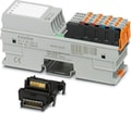
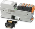
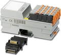
AXL F AI2 AO2 XC 1H - Analog module
Axioline F, Analog I/O module, Analog inputs: 2, 0 V ... 5 V, -5 V ... 5 V, 0 V ... 10 V, -10 V ... 10 V, 0 mA ... 20 mA, 4 mA ... 20 mA, -20 mA ... 20 mA, connection technology: 2-conductor, Analog outputs: 2, 0 V ... 5 V, -5 V ... 5 V, 0 V ... 10 V, -10 V ... 10 V, 0 mA ... 20 mA, 4 mA ... 20 mA, -20 mA ... 20 mA, connection technology: 2-conductor, transmission speed in the local bus: 100 Mbps, Extreme conditions version, degree of protection: IP20, including bus base module and Axioline F connectors
- 2 analog differential input channels
- Connection of sensors in 2-conductor technology
- Current ranges: 0 mA ... 20 mA, 4 mA ... 20 mA, ±20 mA
- Voltage ranges: 0 V ... 10 V, ±10 V, 0 V ... 5 V, ±5 V
- 2 analog outputs
- Connection of actuators in 2-conductor technology
- Current ranges: 0 mA ... 20 mA, 4 mA ... 20 mA, ±20 mA
- Voltage ranges: 0 V ... 10 V, ±10 V, 0 V ... 5 V, ±5 V
- Process data update < 150 µs
- Device rating plate stored
- Can be used under extreme ambient conditions
- Extended temperature range of -40 °C ... +70 °C (see “Tested successfully: use under extreme ambient conditions” in the data sheet)
- Partially coated PCBs
Dimensions
| Width | 35 mm |
| Height | 126.1 mm |
| Depth | 54 mm |
| Note on dimensions | The depth applies when a TH 35-7.5 DIN rail is used (in accordance with EN 60715). |
Axioline F local bus
| Number of interfaces | 2 |
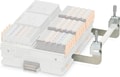
| Connection Method | Bus base module |
| Transmission Speed | 100 Mbps |
Module
| Input address area | 4 Byte |
| Output address area | 4 Byte |
| Required parameter data | 11 Byte |
| Required configuration data | 7 Byte |
Analog: General
| Input name | Analog inputs |
| Description of the input | Differential inputs, voltage or current can be chosen separately |
| Number of Inputs | 2 |
| A/D conversion time | 2 µs |
| A/D converter resolution | 16 bit |
| Connection Method | Push-in connection |
| Connection technology | 2-conductor |
| Note regarding the connection technology | shielded, twisted pair |
| Current Input Signal | 0 mA ... 20 mA |
| Current Input Signal | 4 mA ... 20 mA |
| Current Input Signal | -20 mA ... 20 mA |
| Input resistance current input | 104 Ω (typical) |
| Voltage input signal | 0 V ... 5 V |
| Voltage input signal | -5 V ... 5 V |
| Voltage input signal | 0 V ... 10 V |
| Voltage input signal | -10 V ... 10 V |
| Input resistance of voltage input | 268 kΩ (typical) |
| Data formats | IB IL, S7-compatible, standardized representation |
| Input filter | 30 Hz, 12 kHz and mean-value generation (can be parameterized) |
| Limit frequency (3 dB) | 30 Hz |
| Limit frequency (3 dB) | 12 kHz |
| Common mode voltage range signal - ground | -50 V DC ... 50 V DC |
| Measured value representation | 16 bits (15 bits + sign bit) |
| Protective circuit | Transient protection of inputs; Suppressor diode |
| Protective circuit | Overload protection of the current inputs; No; ±5.2 V DC, maximum, Imax = 50 mA |
| Protective circuit | Overload protection of the voltage inputs; ±30 V DC, maximum |
Analog:
| Output name | Analog outputs |
| Connection Method | Push-in connection |
| Connection technology | 2-conductor |
| Note regarding the connection technology | shielded, twisted pair |
| Number of Outputs | 2 |
| D/A converter resolution | 16 bit |
| Protective circuit | Short-circuit and overload protection; electronic |
| Protective circuit | Transient protection; Suppressor diode |
| Data formats | IB IL, S7-compatible, standardized representation |
| Representation of output values | 16 bits (15 bits + sign) |
| Process data update | 150 µs |
| Current Output Signal | 0 mA ... 20 mA |
| Current Output Signal | 4 mA ... 20 mA |
| Current Output Signal | -20 mA ... 20 mA |
| Load/Output Load Current Output | ≤ 500 Ω |
| Voltage output signal | 0 V ... 5 V |
| Voltage output signal | -5 V ... 5 V |
| Voltage output signal | 0 V ... 10 V |
| Voltage output signal | -10 V ... 10 V |
| Load/output load voltage output | ≥ 2 kΩ |
Product properties
| Product family | Axioline F |
| Type | block modular |
| Mounting Position | any (no temperature derating) |
| Scope of delivery | including bus base module and Axioline F connectors |
| Special Properties | Extreme conditions version |
Insulation characteristics
| Overvoltage category | II (IEC 60664-1, EN 60664-1) |
| Pollution degree | 2 (IEC 60664-1, EN 60664-1) |
Potentials
| Power consumption | typ. 1.56 W (at UBus and UA) |
| Power consumption | max. 2.67 W (at UBus and UA) |
Potentials: Axioline F local bus supply (UBus)
| Supply Voltage | 5 V DC (via bus base module) |
| Current draw | max. 150 mA |
| Current draw | typ. 120 mA |
| Power consumption | max. 0.75 W |
| Power consumption | typ. 0.6 W |
Potentials: Supply for analog modules (UA)
| Supply Voltage | 24 V DC |
| Supply Voltage Range | 19.2 V DC ... 30 V DC (including all tolerances, including ripple) |
| Current draw | max. 80 mA (2 current channels, 24 mA output, 500 Ω load) |
| Current draw | typ. 40 mA |
| Current draw | max. 60 mA (2 voltage channels, 10 V output, 2 kΩ load) |
| Power consumption | max. 1.92 W |
| Protective circuit | Surge protection; electronic (35 V, 0.5 s) |
| Protective circuit | Reverse polarity protection; Polarity protection diode |
| Protective circuit | Transient protection; Suppressor diode |
Electrical isolation/isolation of the voltage ranges
| Test voltage: 5 V supply of the local bus (UBus) / 24 V supply (I/Os) | 500 V AC, 50 Hz, 1 min. |
| Test voltage: 5 V supply of the local bus (UBus) / analog inputs and outputs | 500 V AC, 50 Hz, 1 min. |
| Test voltage: 5 V supply of the local bus (UBus) / functional ground | 500 V AC, 50 Hz, 1 min. |
| Test voltage: 24 V supply (I/O) / analog inputs and outputs | 500 V AC, 50 Hz, 1 min. |
| Test voltage: 24 V supply (I/O) / functional ground | 500 V AC, 50 Hz, 1 min. |
| Test voltage: Analog inputs and outputs/functional ground | 500 V AC, 50 Hz, 1 min. |
Connection technology
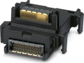
| Connection name | Axioline F connector |
| Note on the connection method | Please observe the information provided on conductor cross sections in the “Axioline F: system and installation” user manual. |
| Note on the connection method | Applications with UL approval: only use copper conductors. |
Conductor connection
| Connection Method | Push-in connection |
| Conductor cross section rigid | 0.2 mm² ... 1.5 mm² |
| Conductor cross section flexible | 0.2 mm² ... 1.5 mm² |
| Conductor cross section AWG | 24 ... 16 |
| Stripping length | 8 mm |
Axioline F connector
| Connection Method | Push-in connection |
| Note on the connection method | Please observe the information provided on conductor cross sections in the “Axioline F: system and installation” user manual. |
| Note on the connection method | Applications with UL approval: only use copper conductors. |
| Conductor cross section, rigid | 0.2 mm² ... 1.5 mm² |
| Conductor cross section, flexible | 0.2 mm² ... 1.5 mm² |
| Conductor cross section AWG | 24 ... 16 |
| Stripping length | 8 mm |
Ambient conditions
| Ambient Temperature (Operation) | -25 °C ... 60 °C (Standard applications and applications with UL approval) |
| Ambient Temperature (Operation) | -40 °C ... 70 °C (Extended, see section “Tested successfully: use under extreme ambient conditions” in the data sheet.) |
| Degree of Protection | IP20 |
| Air pressure (operation) | 70 kPa ... 106 kPa (up to 3000 m above sea level) |
| Air pressure (storage/transport) | 70 kPa ... 106 kPa (up to 3000 m above sea level) |
| Ambient temperature (storage/transport) | -40 °C ... 85 °C |
| Permissible humidity (operation) | 5 % ... 95 % (non-condensing) |
| Permissible humidity (storage/transport) | 5 % ... 95 % (non-condensing) |
Standards and Regulations
| Protection class | III (IEC 61140, EN 61140, VDE 0140-1) |
Mounting
| Mounting Type | DIN rail mounting |
| Mounting Position | any (no temperature derating) |


Why Proax for Phoenix Contact 1035429?
Proax is an authorized distributor of Phoenix Contact 1035429 and one of Phoenix Contact's largest distributors in North America. Our highly skilled in-house technical team is ready to assist with any technical needs.
Have a question in mind? to help you get the right product as quickly as possible for your project. We're always here to help!
| Pack Size | 1 |

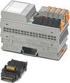
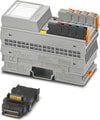
 AXL F AI2 AO2 1H - Axioline F, Analog I/O module, Analog inputs: 2, 0 V ... 5 V, -5 V ... 5 V, 0 V ... 10 V, -10 V ... 10 V, 0 mA ... 20 mA, 4 mA ... 20 mA, -20 mA ... 20 mA, connection technology: 2-conductor, Analog outputs: 2, 0 V ... 5 V, -5 V ... 5 V, 0 V ... 10 V, -10 V ... 10 V, 0 mA ... 20 mA, 4 mA ... 20 mA, -20 mA ... 20 mA, connection technology: 2-conductor, transmission speed in the local bus: 100 Mbps, degree of protection: IP20, including bus base module and Axioline F connectors
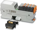 AXL F AI4 I 1H - Axioline F, Analog input module, Analog inputs: 4, 0 mA ... 20 mA, 4 mA ... 20 mA, -20 mA ... 20 mA, connection technology: 2-, 3-, 4-conductor, transmission speed in the local bus: 100 Mbps, integrated sensor supply, degree of protection: IP20, including bus base module and Axioline F connectors
- AXL F AI4 I XC 1H - Axioline F, Analog input module, Analog inputs: 4, 0 mA ... 20 mA, 4 mA ... 20 mA, -20 mA ... 20 mA, connection technology: 2-, 3-, 4-conductor, transmission speed in the local bus: 100 Mbps, integrated sensor supply, Extreme conditions version, degree of protection: IP20, including bus base module and Axioline F connectors
 AXL F AI4 U 1H - Axioline F, Analog input module, Analog inputs: 4, 0 V ... 5 V, -5 V ... 5 V, 0 V ... 10 V, -10 V ... 10 V, connection technology: 2-, 3-, 4-conductor, transmission speed in the local bus: 100 Mbps, integrated sensor supply, degree of protection: IP20, including bus base module and Axioline F connectors
- AXL F AI4 U XC 1H - Axioline F, Analog input module, Analog inputs: 4, 0 V ... 5 V, -5 V ... 5 V, 0 V ... 10 V, -10 V ... 10 V, connection technology: 2-, 3-, 4-conductor, transmission speed in the local bus: 100 Mbps, integrated sensor supply, Extreme conditions version, degree of protection: IP20, including bus base module and Axioline F connectors
 AXL F AI8 HART XC 1F - Axioline F, Analog input module, Active analog inputs: 8 (HART), 4 mA ... 20 mA, connection technology: 2-conductor, transmission speed in the local bus: 100 Mbps, Extreme conditions version, HART functionality, degree of protection: IP20, including bus base module and Axioline F connectors
 AXL F AI8 1F - Axioline F, Analog input module, Analog inputs: 8, 0 V ... 5 V, -5 V ... 5 V, 0 V ... 10 V, -10 V ... 10 V, 0 mA ... 20 mA, 4 mA ... 20 mA, -20 mA ... 20 mA, connection technology: 2-conductor, transmission speed in the local bus: 100 Mbps, degree of protection: IP20, including bus base module and Axioline F connectors
- Axioline F, Analog input module, Analog inputs: 8, 0 V ... 5 V, -5 V ... 5 V, 0 V ... 10 V, -10 V ... 10 V, 0 mA ... 20 mA, 4 mA ... 20 mA, -20 mA ... 20 mA, connection technology: 2-conductor, transmission speed in the local bus: 100 Mbps, Extreme conditions version, degree of protection: IP20, including bus base module and Axioline F connectors
- AXL F AI8 W 1F - Axioline F, Analog input module, Analog inputs: 8, 0 V ... 5 V, -5 V ... 5 V, 0 V ... 10 V, -10 V ... 10 V, 0 mA ... 20 mA, 4 mA ... 20 mA, -20 mA ... 20 mA, connection technology: 2-conductor, transmission speed in the local bus: 100 Mbps, for SAFE AI applications with service-free continuous operation, degree of protection: IP20, including bus base module and Axioline F connectors
 Axioline F, Analog output module, Analog outputs: 4 (HART), 0 mA ... 20 mA, 4 mA ... 20 mA, connection technology: 2-conductor, transmission speed in the local bus: 100 Mbps, Extreme conditions version, HART functionality, degree of protection: IP20, including bus base module and Axioline F connectors
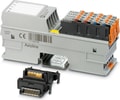 Axioline F, Analog output module, Analog outputs: 4, 0 V ... 5 V, -5 V ... 5 V, 0 V ... 10 V, -10 V ... 10 V, 0 mA ... 20 mA, 4 mA ... 20 mA, connection technology: 2-conductor, transmission speed in the local bus: 100 Mbps, degree of protection: IP20, including bus base module and Axioline F connectors
- AXL F AO4 XC 1H - Axioline F, Analog output module, Analog outputs: 4, 0 V ... 5 V, -5 V ... 5 V, 0 V ... 10 V, -10 V ... 10 V, 0 mA ... 20 mA, 4 mA ... 20 mA, connection technology: 2-conductor, transmission speed in the local bus: 100 Mbps, Extreme conditions version, degree of protection: IP20, including bus base module and Axioline F connectors
 AXL F AO8 1F - Axioline F, Analog output module, Analog outputs: 8, 0 V ... 5 V, -5 V ... 5 V, 0 V ... 10 V, -10 V ... 10 V, 0 mA ... 20 mA, 4 mA ... 20 mA, -20 mA ... 20 mA, connection technology: 2-conductor, transmission speed in the local bus: 100 Mbps, degree of protection: IP20, including bus base module and Axioline F connectors
- AXL F AO8 XC 1F - Axioline F, Analog output module, Analog outputs: 8, 0 V ... 5 V, -5 V ... 5 V, 0 V ... 10 V, -10 V ... 10 V, 0 mA ... 20 mA, 4 mA ... 20 mA, -20 mA ... 20 mA, connection technology: 2-conductor, transmission speed in the local bus: 100 Mbps, Extreme conditions version, degree of protection: IP20, including bus base module and Axioline F connectors
 AXL F BK EC - Axioline F, Bus coupler, EtherCAT®, RJ45 jack, transmission speed in the local bus: 100 Mbps, degree of protection: IP20, including bus base module and Axioline F connector
 AXL F BK EIP - Axioline F, Bus coupler, EtherNet/IP™, RJ45 jack, transmission speed in the local bus: 100 Mbps, degree of protection: IP20, including bus base module and Axioline F connector
- Axioline F, Bus coupler, EtherNet/IP™, RJ45 jack, extended function, transmission speed in the local bus: 100 Mbps, degree of protection: IP20, including bus base module and Axioline F connector
 Axioline F, Bus coupler, EtherNet/IP™, RJ45 jack, Extreme conditions version, transmission speed in the local bus: 100 Mbps, degree of protection: IP20, including bus base module and Axioline F connector
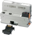 AXL F BK ETH - Axioline F, Bus coupler, Modbus/TCP(UDP), RJ45 jack, transmission speed in the local bus: 100 Mbps, degree of protection: IP20, including bus base module and Axioline F connector
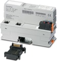 AXL F BK ETH NET2 - Axioline F, Bus coupler, Ethernet (2 networks), RJ45 jack, transmission speed in the local bus: 100 Mbps, degree of protection: IP20, including bus base module and Axioline F connector