2986012
 Official Distributor
SKU
PHX2986012
MPN
PSR-SCP- 24DC/TS/M
Weight
0.416 kg
This product is Not Cancellable/Not Returnable
Series PSR-SCP
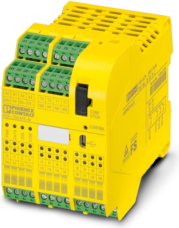
PSR-SCP- 24DC/TS/M - Safety module
Freely configurable safety module with 20 safe inputs and 4 safe outputs; 4 alarm, 2 clock, and 2 ground switching outputs; can be extended with additional I/O modules, up to SIL 3, Cat.4/PL e, SIL 3, EN 50156, plug-in screw connection terminal blocks
- Freely configurable safety module for monitoring emergency stops, safety doors, light grids, etc.
- Up to Cat. 4/PL e in accordance with ISO 13849-1, SIL 3 in accordance with EN IEC 62061, SIL 3 in accordance with IEC 61508
- EN 50156
- Flexible extension with safe inputs and outputs
- Quick startup thanks to comprehensive simulation and test functions
- Easy graphical configuration instead of complex programming
- Safe and standard extension via INTERFACE DIN rail TBUS
- Option for connecting fieldbus gateways for diagnostics and signaling functions
- Easy graphical configuration with the SAFECONF software
- Including IFS-CONFSTICK memory stick for easily storing and saving the configuration
- Multifunctional use for a wide range of safety functions
- With 20 safe inputs, 4 safe outputs, 4 alarm outputs, and 2 clock outputs on a design width of just 67.5 mm
Technical Specifications
Product properties
| Application | Emergency stop |
| Application | Light grid |
| Application | Safety door |
| Application | Two-hand control |
| Number of possible extension modules | 1 (max. continuous current via PSR-TBUS: 4 A) |
| Number of possible safe extension modules | 10 (max. continuous current via PSR-TBUS: 4 A) |
Insulation characteristics: Air clearances and creepage distances between the power circuits
| Overvoltage category | III |
| Pollution degree | 2 |
Times
| Response time | max. 30 ms (plus response time of PSR-TS-SDOR4) |
| Recovery time | < 10 s |
Electrical properties
| Maximum power dissipation for nominal condition | 6372 mW (at a = 20, b = 2, c = 4, e = 2, Iclock = 100 mA, Isignal = 100 mA, IOut/GND = 2 A, IOut/Out = 2 A) |
| Nominal operating mode | 100% operating factor |
| Interfaces | USB |
| Interfaces | DIN rail TBUS for extension modules and bus couplers |
Supply
| Rated control circuit supply voltage US | 18 V DC ... 30 V DC (Incl. all tolerances, incl. residual ripple) |
| Rated control circuit supply voltage US | 24 V DC (A1/A2) |
| Rated control supply current IS | typ. 110 mA |
| Limiting Continuous Current | max. 6 A (For looped-through current paths A1/A1 and A2/A2) |
| Filter time | typ. 20 ms (Load-dependent, in the event of voltage dips at US) |
| Protective circuit | Yes, within the scope of the operating voltage limits |
| Status display | 3x LED green, 1x LED red |
Digital
| Description of the input | Digital, type HTL |
| Number of Inputs | 10 (Two-channel, up to SIL 3) |
| Number of Inputs | 20 (Single-channel, up to SIL 2) |
| Input voltage range "0" signal | 0 V DC ... 5 V DC (for safe Off) |
| Input voltage range "1" signal | 11 V DC ... 30 V DC |
| Cable Length | max. 2000 m |
| Status display | 20 x LED green (1 LED per input) |
| Current consumption | typ. 4 mA |
| Number of Outputs | 4 (Safe semiconductor outputs, up to Cat. 4 in accordance with EN ISO 13849-1) |
| Number of Outputs | 2 (Ground switching outputs) |
| Note on protection circuit | Yes, within the scope of the operating voltage limits |
| Short-circuit protection | Yes |
| Output Voltage | < 5 V (Low state) |
| Leakage current | max. 2 mA |
| Max. capacitive load | max. 1 µF (Electronic components) |
| Max. inductive load | See "Protective circuit" |
| Limiting Continuous Current | 2 A (Per channel, see Derating) |
| Limiting Continuous Current | 2 A (Total current of all outputs) |
| Nominal Output Voltage | 24 V DC (Supply via 24 V/0 V) |
| Nominal output voltage range | 18 V DC ... 30 V DC (Incl. all tolerances, incl. residual ripple) |
| Status display | 4 x LED green (1 LED per output) |
| Test pulses | < 1 ms |
Signal
| Output description | Digital |
| Number of Outputs | 4 |
| Voltage | 24 V DC (Supply via 24 V/0 V) |
| Limiting Continuous Current | 100 mA |
| Short-circuit protection | Yes |
Clock
| Output description | Digital |
| Number of Outputs | 2 |
| Voltage | 24 V DC (Supply via 24 V/0 V) |
| Limiting Continuous Current | 100 mA |
| Test pulses | < 1 ms |
| Short-circuit protection | Yes |
Connection technology
| pluggable | yes |
Conductor connection
| Connection Method | Screw connection |
| Conductor cross section rigid | 0.2 mm² ... 2.5 mm² |
| Conductor cross section flexible | 0.2 mm² ... 2.5 mm² |
| Conductor cross-section AWG | 24 ... 12 |
| Stripping length | 7 mm |
| Screw thread | M3 |
| Tightening torque | 0.5 Nm ... 0.6 Nm |
| Tightening torque | 5 lbf-in. ... 7 lbf-in. |
Dimensions
| Width | 67.5 mm |
| Height | 99 mm |
| Depth | 114.5 mm |
Material specifications
| Color | yellow |
| Housing Material | Polyamide PA non-reinforced |
Safety data
| Stop category | 0 |
Safety data: EN ISO 13849
| Category | 2 (1-channel parameterization) |
| Category | 4 (2-channel parameterization) |
| Performance level (PL) | d (1-channel parameterization) |
| Performance level (PL) | e (2-channel parameterization) |
Safety data: EN 50156
| Safety Integrity Level (SIL) | max. 3 (Reference IEC 61508) |
Safety data: IEC 61508 - High demand
| Safety Integrity Level (SIL) | 2 (1-channel parameterization) |
| Safety Integrity Level (SIL) | 3 (2-channel parameterization) |
Safety data: IEC 61508 - Low demand
| Safety Integrity Level (SIL) | 2 (1-channel parameterization) |
| Safety Integrity Level (SIL) | 3 (2-channel parameterization) |
Safety data: EN IEC 62061
| Safety Integrity Level (SIL) | 2 (1-channel parameterization) |
| Safety Integrity Level (SIL) | 3 (2-channel parameterization) |
Ambient conditions
| Degree of Protection | IP20 |
| Min. degree of protection of inst. location | IP54 |
| Ambient Temperature (Operation) | -20 °C ... 55 °C |
| Ambient temperature (storage/transport) | -20 °C ... 70 °C |
| Maximum altitude | max. 2000 m (See Appendix "Using PSR-TRISAFE modules at altitudes greater than 2000 m above sea level") |
| Max. permissible humidity (storage/transport) | 75 % (On average, 85 % occasionally) |
| Max. permissible relative humidity (operation) | 75 % (On average, 85 % occasionally) |
| Shock (operation) | 10g (Δt = 11 ms, three shocks in each space direction) |
| Shock (operation) | 10g (Δt = 16 ms, continuous shock, 1000 shocks in each space direction) |
| Vibration (Operation) | 2g |
| Air pressure (operation) | 70 kPa ... 108 kPa (up to 3000 m above sea level) |
| Air pressure (storage/transport) | 66 kPa ... 108 kPa (up to 3500 m above sea level) |
Air clearances and creepage distances between the power circuits
| Standards/regulations | DIN EN 50178 |
Mounting
| Mounting Type | DIN rail mounting |
| Mounting Position | On horizontal DIN rail |
Accessories
 ME 22,5 TBUS 1,5/ 5-ST-3,81 GN - DIN rail connector, color: green, nominal current: 8 A (parallel contacts), rated voltage (III/2): 125 V, number of positions: 5, product range: TBUS5-22,5.., pitch: 3.81 mm, mounting: DIN rail mounting, locking: without, mounting: without, type of packaging: packed in cardboard, Item with gold-plated contacts, bus connectors for connecting with electronics housings, 5 parallel contacts
Why Proax for Phoenix Contact 2986012?
Proax is an authorized distributor of Phoenix Contact 2986012 and one of Phoenix Contact's largest distributors in North America. Our highly skilled in-house technical team is ready to assist with any technical needs.
Have a question in mind? to help you get the right product as quickly as possible for your project. We're always here to help!
Short Lead Time
Highly Trained Staff
Live Chat
Technical Support
Local Inventory
60+ Years Experience
Additional Information
| Pack Size | 1 |
Recommended
 PSR-SCP- 24DC/FSP2/2X1/1X2 - Safe coupling relay for SIL 2 high- and low-demand applications, couples digital output signals to the periphery, two enabling current paths, one signal contact, module for safe state off applications, integrated test pulse filter, plug-in screw connection, width: 17.5 mm
 PSR-SCP- 24DC/FSP/2X1/1X2 - Safe coupling relay for SIL 3 high- and low-demand applications, couples digital output signals to the periphery, two enabling current paths, one signal contact, module for safe state off applications, integrated test pulse filter, plug-in screw connection, width: 17.5 mm


