Featured
2903154
 Official Distributor
SKU
PHX2903154
MPN
TRIO-PS-2G/3AC/24DC/10
Series TRIO-PS
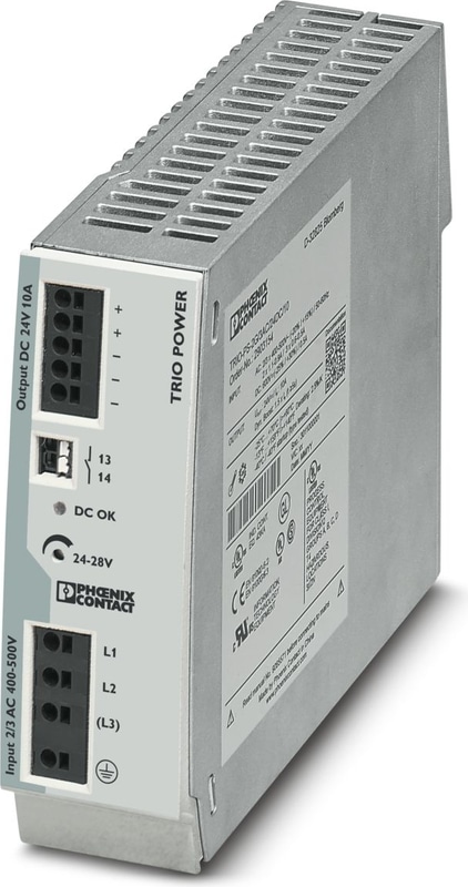
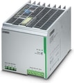
TRIO-PS-2G/3AC/24DC/10 - Power supply unit
Primary-switched TRIO POWER power supply with push-in connection for DIN rail mounting, input: 3-phase, output: 24 V DC/10 A
- Save time and costs, thanks to the Push-in connection and narrow design
- Increase system availability, thanks to dynamic boost with 150% of the nominal current for five seconds
- Maximum flexibility due to the wide temperature range from -25°C to +70°C and device startup at -40°C
- Rugged design
Technical Specifications
AC operation
| Network Type | Star network |
| Nominal input voltage range | 3x 400 V AC ... 500 V AC |
| Nominal input voltage range | 2x 400 V AC ... 500 V AC |
| Input voltage range | 3x 400 V AC ... 500 V AC -20 % ... +15 % |
| Input voltage range | 2x 400 V AC ... 500 V AC -10 % ... +15 % |
| Input Voltage Range AC | 3x 320 V AC ... 575 V AC |
| Typical national grid voltage | 3x 400 V AC |
| Typical national grid voltage | 3x 480 V AC |
| Voltage type of supply voltage | AC |
| Inrush Current | ≤ 26 A (typical) |
| Inrush current integral (I2t) | ≤ 0.3 A2s |
| AC frequency range | 50 Hz ... 60 Hz |
| Mains buffering time | typ. 10 ms (400 V AC) |
| Mains buffering time | typ. 20 ms (500 V AC) |
| Current consumption | 3x 0.6 A (400 V AC) |
| Current consumption | 3x 0.6 A (500 V AC) |
| Current consumption | 2x 1.1 A (400 V AC) |
| Current consumption | 2x 1.1 A (500 V AC) |
| Nominal Power Consumption | 451.7 VA |
| Protective circuit | Transient surge protection; Varistor |
| Power factor (cos phi) | 0.58 |
| Typical response time | < 1 s |
| Input fuse | 3.15 A (internal (device protection), slow-blow) |
| Recommended breaker for input protection | 6 A ... 16 A (Characteristics B, C, D, K) |
| Discharge current to PE | < 3.5 mA |
| Discharge current to PE | < (550 V AC, 60 Hz) |
Output data
| Efficiency | > 92 % (at 400 V AC and nominal values) |
| Output characteristic | U/I with dynamic load reserve |
| Nominal Output Voltage | 24 V DC ±1 % |
| Setting range of the output voltage (USet) | 24 V DC ... 28 V DC (> 24 V DC, constant capacity restricted) |
| Nominal output current (IN) | 10 A |
| Dynamic Boost (IDyn.Boost) | 15 A (5 s) |
| Derating | > 60 °C ... 70 °C (2.5 %/K) |
| Protection against overvoltage at the output (OVP) | ≤ 30 V DC |
| Control deviation | < 1 % (change in load, static 10 % ... 90 %) |
| Control deviation | < 3 % (Dynamic load change 10 % ... 90 %, 10 Hz) |
| Control deviation | < 0.1 % (change in input voltage ±10 %) |
| Residual ripple | ≤ 20 mVPP |
| Short-circuit-proof | yes |
| No-load proof | yes |
| Output Power | 240 W |
| Output Power | 360 W |
| Maximum no-load power dissipation | < 1.1 W (400 V AC) |
| Power loss nominal load max. | < 22 W (480 V AC) |
| Rise time | ≤ 120 ms (UOUT (10 % ... 90 %)) |
| Connection in parallel | yes, for redundancy and increased capacity |
| Connection in series | yes |
Signal: DC OK
| Continuous load current | 100 mA |
Signal relay 13/14
| Default | closed |
| Digital | 30 V AC 30 V DC 100 mA |
Input
| Connection Method | Push-in connection |
| Conductor cross section, rigid min. | 0.2 mm² |
| Conductor cross section, rigid max. | 4 mm² |
| Conductor cross section flexible min. | 0.2 mm² |
| Conductor cross section flexible max. | 2.5 mm² |
| Single conductor/terminal point, stranded, with ferrule, min. | 0.2 mm² |
| Single conductor/terminal point, stranded, with ferrule, max. | 2.5 mm² |
| Conductor cross section AWG min. | 24 |
| Conductor cross section AWG max. | 12 |
| Stripping length | 10 mm |
Output
| Connection Method | Push-in connection |
| Conductor cross section, rigid min. | 0.2 mm² |
| Conductor cross section, rigid max. | 4 mm² |
| Conductor cross section flexible min. | 0.2 mm² |
| Conductor cross section flexible max. | 2.5 mm² |
| Single conductor/terminal point, stranded, with ferrule, min. | 0.2 mm² |
| Single conductor/terminal point, stranded, with ferrule, max. | 2.5 mm² |
| Conductor cross section AWG min. | 24 |
| Conductor cross section AWG max. | 12 |
| Stripping length | 10 mm |
Signal
| Connection Method | Push-in connection |
| Conductor cross section, rigid min. | 0.2 mm² |
| Conductor cross section, rigid max. | 1.5 mm² |
| Conductor cross section flexible min. | 0.2 mm² |
| Conductor cross section flexible max. | 1.5 mm² |
| Single conductor/terminal point, stranded, with ferrule, min. | 0.2 mm² |
| Single conductor/terminal point, stranded, with ferrule, max. | 1.5 mm² |
| Conductor cross section AWG min. | 24 |
| Conductor cross section AWG max. | 16 |
| Stripping length | 8 mm |
Signaling
| Types of signaling | LED |
| Types of signaling | Floating signal contact |
Signal output: LED status indicator
| Signalization designation | DC OK |
| Status display | LED |
| Color | green |
| DC OK | UOUT > 0.9 x UN (UN = 24 V DC) |
Electrical properties
| Number of phases | 3.00 |
| Insulation voltage input/output | 3 kV AC (type test) |
| Insulation voltage input/output | 1.5 kV AC (routine test) |
Product properties
| Product family | TRIO POWER |
| MTBF (IEC 61709, SN 29500) | > 2100000 h (25 °C) |
| MTBF (IEC 61709, SN 29500) | > 1200000 h (40 °C) |
| MTBF (IEC 61709, SN 29500) | > 590000 h (60 °C) |
Insulation characteristics
| Protection class | I (in closed control cabinet) |
| Degree of pollution | 2 |
Dimensions
| Width | 42 mm |
| Height | 130 mm |
| Depth | 160 mm |
Installation dimensions
| Installation distance right/left | 0 mm / 0 mm |
| Installation distance top/bottom | 50 mm / 50 mm |
Mounting
| Mounting Type | DIN rail mounting |
| Assembly instructions | alignable: horizontally 0 mm (≤ 40 °C) 10 mm (≤ 70 °C), vertically 50 mm |
| Mounting Position | horizontal DIN rail NS 35, EN 60715 |
| With protective coating | No |
Material specifications
| Flammability rating according to UL 94 (housing / terminal blocks) | V0 |
| Housing Material | Metal |
| Type of housing | Aluminum (AlMg3) |
| Hood version | Polycarbonate |
Ambient conditions
| Degree of Protection | IP20 |
| Ambient Temperature (Operation) | -25 °C ... 70 °C (> 60 °C Derating: 2,5 %/K) |
| Ambient temperature (storage/transport) | -40 °C ... 85 °C |
| Ambient temperature (start-up type tested) | -40 °C |
| Maximum altitude | ≤ 5000 m (> 2000 m, Derating: 10 %/1000 m) |
| Climatic class | 3K3 (in acc. with EN 60721) |
| Max. permissible relative humidity (operation) | ≤ 95 % (at 25 °C, non-condensing) |
| Shock | 18 ms, 30g, in each space direction (according to IEC 60068-2-27) |
| Vibration (Operation) | < 15 Hz, amplitude ±2.5 mm (according to IEC 60068-2-6) |
| Vibration (Operation) | 15 Hz ... 150 Hz, 4g, 90 min. |
Standards and Regulations
| Rail applications | EN 50121-4 |
| Standard – Electronic equipment for use in electrical power installations and their assembly into electrical power installations | EN 50178/VDE 0160 (PELV) |
| Standard – Limitation of mains harmonic currents | EN 61000-3-2 |
| Standard - Electrical safety | IEC 62368-1 (SELV) |
| Standard – Safety extra-low voltage | IEC 62368-1 (SELV) und EN 60204-1 (PELV) |
| Standard - Safe isolation | DIN VDE 0100-410 |
| Standard - Safety of transformers | EN 61558-2-16 (air clearances and creepage distances only) |
Approvals
| UL approvals | UL Listed UL 508 |
| UL approvals | UL/C-UL Recognized UL 60950-1 |
Conformity/Approvals
| SIL in accordance with IEC 61508 | 0 |
EMC data
| Low Voltage Directive | Conformance with Low Voltage Directive 2014/35/EC |
| EMC requirements for noise emission | EN 61000-6-3 |
| EMC requirements for noise emission | EN 61000-6-4 |
| EMC requirements for noise immunity | EN 61000-6-1 |
| EMC requirements for noise immunity | EN 61000-6-2 |
| Electromagnetic compatibility | Conformance with EMC Directive 2014/30/EU |
| Conducted noise emission | EN 55016 |
| Conducted noise emission | EN 61000-6-3 (Class B) |
| Noise emission | EN 55011 (EN 55022) |
Electrostatic discharge
| Standards/regulations | EN 61000-4-2 |
| Contact discharge | 6 kV (Test Level 4) |
| Discharge in air | 8 kV (Test Level 4) |
| Comments | Criterion A |
Electromagnetic HF field
| Standards/regulations | EN 61000-4-3 |
| Frequency Range | 80 MHz ... 1 GHz |
| Test field strength | 10 V/m (Test Level 3) |
| Frequency Range | 1 GHz ... 2 GHz |
| Test field strength | 10 V/m (Test Level 3) |
| Frequency Range | 2 GHz ... 3 GHz |
| Test field strength | 10 V/m (Test Level 3) |
| Comments | Criterion A |
Fast transients (burst)
| Standards/regulations | EN 61000-4-4 |
| Input | 4 kV (Test Level 4 - asymmetrical) |
| Output | 2 kV (Test Level 3 - asymmetrical) |
| Signal | 1 kV (Test Level 2 - asymmetrical) |
| Comments | Criterion A |
Surge voltage load (surge)
| Standards/regulations | EN 61000-4-5 |
| Input | 1 kV (Test Level 1 - symmetrical) |
| Input | 2 kV (Test Level 1 - asymmetrical) |
| Output | 0.5 kV (Test Level 1 - symmetrical) |
| Output | 0.5 kV (Test Level 1 - asymmetrical) |
| Signal | 1 kV (Test Level 2 - asymmetrical) |
| Comments | Criterion B |
Conducted interference
| Standards/regulations | EN 61000-4-6 |
| Input/Output | asymmetrical |
| Frequency Range | 0.15 MHz ... 80 MHz |
| Comments | Criterion A |
| Voltage | 10 V (Test Level 3) |
Emitted interference
| Standards/regulations | EN 61000-6-3 |
| Radio interference voltage in acc. with EN 55011 | EN 55011 (EN 55022) Class B, area of application: Industry and residential |
| Emitted radio interference in acc. with EN 55011 | EN 55011 (EN 55022) Class B, area of application: Industry and residential |
Criteria
| Criterion A | Normal operating behavior within the specified limits. |
| Criterion B | Temporary impairment to operational behavior that is corrected by the device itself. |
Accessories
Why Proax for Phoenix Contact 2903154?
Proax is an authorized distributor of Phoenix Contact 2903154 and one of Phoenix Contact's largest distributors in North America. Our highly skilled in-house technical team is ready to assist with any technical needs.
Have a question in mind? to help you get the right product as quickly as possible for your project. We're always here to help!
Short Lead Time
Highly Trained Staff
Live Chat
Technical Support
Local Inventory
60+ Years Experience
Additional Information
| Pack Size | 1 |
Recommended
 TRIO-PS/1AC/5DC/10, TRIO POWER power supplies with standard functionalityTRIO POWER is particularly suited to standard machine production, thanks to 1- and 3-phase versions up to 960 W. The wide-range input and the international approval package enable worldwide use.The robust metal housing, the high electric strength, and the wide temperature range ensure a high level of power supply reliability.
 TRIO-PS/1AC/48DC/ 5, TRIO POWER power supplies with standard functionalityTRIO POWER is particularly suited to standard machine production, thanks to 1- and 3-phase versions up to 960 W. The wide-range input and the international approval package enable worldwide use.The robust metal housing, the high electric strength, and the wide temperature range ensure a high level of power supply reliability.
 TRIO-PS/3AC/24DC/40, TRIO POWER power supplies with standard functionalityTRIO POWER is particularly suited to standard machine production, thanks to 1- and 3-phase versions up to 960 W. The wide-range input and the international approval package enable worldwide use.The robust metal housing, the high electric strength, and the wide temperature range ensure a high level of power supply reliability.


