2924689
SKU
PHX2924689
MPN
MACX MCR-EX-T-UI-UP-SP
Weight
0.269 kg
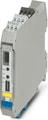
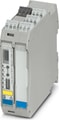
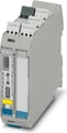
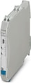
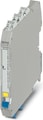
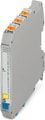
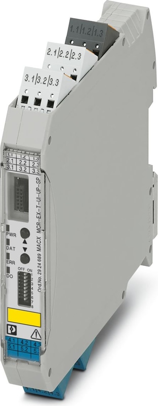
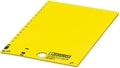
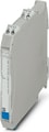
MACX MCR-EX-T-UI-UP-SP - Temperature measuring transducer
Programmable Ex-i temperature transducer with analog output and 1 limit value relay, standard configuration, resistance thermometer in 2-, 3-, or 4-conductor technology, thermocouples, electrical isolation, wide-range power supply, Push-in connection, SIL, PL.
- Input for resistance thermometers, thermocouples, resistance-type sensors, potentiometers, and mV sources, [Ex ia] IIC
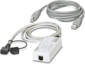
- Programming during operation with Ex measuring circuit connected and also voltage-free using IFS-USB-PROG-ADAPTER programming adapter
- Cold junction compensation with separate plug
- Configuration via software (FDT/DTM) or IFS-OP-UNIT operator interface and display unit
- Up to SIL 2 in accordance with EN 61508
- Installation in zone 2, protection type "n" (EN 60079-15) permitted
- Plug-in screw or spring-cage connection technology (Push-in technology)
- Status indicator for supply voltage, cable, sensor, and module errors
- Measure differential temperatures
- Wide-range power supply of 19.2 ... 253 V AC/DC
- Freely programmable input and output
- Inverse output signal ranges as an option
- Relay switching output
Technical Specifications
Utilization restriction
| EMC note | EMC: class A product, see manufacturer's declaration in the download area |
Product properties
| Product family | MACX Analog |
| Type | Ex i signal conditioners with SIL and PL Functional Safety |
| Configuration | DIP switches |
| Configuration | Software |
Insulation characteristics
| Overvoltage category | II |
| Pollution degree | 2 |
Electrical properties
| Electrical isolation | 4-way isolation |
| Step response (0–99%) | ≤ 1.75 s (SIL on) |
| Step response (0–99%) | 1.3 s (SIL off) |
| Maximum temperature coefficient | 0.01 %/K |
| Maximum transmission error | 0.1 % (E.g., at Pt 100, 300 K min. span) |
Electrical isolation Input/output/power supply
| Test voltage | 2.5 kV AC (50 Hz, 60 s) |
Electrical isolation Input/output
| Electrical isolation | 375 V (Peak value in accordance with IEC/EN 60079-11) |
Electrical isolation Input/power supply
| Electrical isolation | 375 V (Peak value in accordance with IEC/EN 60079-11) |
Electrical isolation Input/switching output
| Electrical isolation | 375 V (Peak value in accordance with IEC/EN 60079-11) |
Electrical isolation Output/supply
| Rated Insulation Voltage | 300 Vrms |
| Insulation | Safe isolation in accordance with IEC/EN 61010-1 |
Supply
| Nominal supply voltage range | 24 V AC/DC ... 230 V AC/DC (50/60 Hz) |
| Supply Voltage Range | 19.2 V AC/DC ... 253 V AC/DC (24 V AC/DC ... 230 V AC/DC (-20 % ... +10 %, 50/60 Hz)) |
| Typical current consumption | < 50 mA (24 V DC) |
| Power consumption | < 1.5 W |
Signal
| Number of Inputs | 1 |
| Input Signal | Temperature |
| Input Signal | Resistor |
| Input Signal | Voltage |
Measurement
| Sensor types (RTD) that can be used | Pt, Ni, Cu sensors: 2, 3, 4-wire |
| Sensor types that can be used (TC) | B, E, J, K, N, R, S, T, L, U, CA, DA, A1G, A2G, A3G, MG, LG |
| Temperature measuring range | -250 °C ... 2500 °C (Range depending on the sensor type) |
| Linear resistance measuring range | 0 Ω ... 50 kΩ |
| Potentiometer resistance range | 0 Ω ... 50 kΩ |
| Linear mV signal range | -1000 mV ... 1000 mV |
Switching: Relay
| Configurable/programmable | Yes |
| Contact switching type | 1 changeover contact |
| Contact Material | AgSnO2, hard gold-plated |
| Maximum Switching Voltage | 30 V AC (30 V DC) |
| Max. switching current | 0.5 A (30 V AC) |
| Max. switching current | 1 A (30 V DC) |
Signal: Voltage/current
| Number of Outputs | 1 |
| Configurable/programmable | Yes |
| Max. voltage output signal | ± 11 V |
| Current Output Signal | 4 mA ... 20 mA (in the case of SIL; further free configuration without SIL) |
| Max. current output signal | 22 mA |
| Load/output load voltage output | ≥ 10 kΩ |
| Load/Output Load Current Output | ≤ 600 Ω (20 mA) |
| Behavior in the event of a sensor error | according to NE 43 or freely configurable |
Connection data
| Connection Method | Push-in connection |
| Stripping length | 8 mm |
| Conductor cross section rigid | 0.2 mm² ... 1.5 mm² |
| Conductor cross section flexible | 0.2 mm² ... 1.5 mm² |
| Conductor cross section AWG | 24 ... 16 |
Ex data
| Ex installation (EPL) | Gc |
| Ex installation (EPL) | Div. 2 |
| Ex i circuits (EPL) | Ga |
| Ex i circuits (EPL) | Da |
| Ex i circuits (EPL) | Ma |
| Ex i circuits (EPL) | Div. 1 |
Safety data
| Max. internal inductance Li | negligible |
| Max. internal capacitance Ci | 44 nF |
| Max. output voltage Uo | 6 V DC |
| Max. output current Io | 7 mA (RTD in 2-conductor technology) |
| Max. output current Io | 13 mA (RTD in 3-conductor technology) |
| Max. output current Io | 16 mA (RTD in 4-conductor technology) |
| Max. output current Io | 13 mA (TC with internal cold junction compensation) |
| Max. output current Io | 10 mA (TC with external cold junction compensation) |
| Max. output current Io | 5 mA (mV) |
| Max. output current Io | 13 mA (Potentiometer) |
| Max. output power Po | 11 mW (RTD in 2-conductor technology) |
| Max. output power Po | 20 mW (RTD in 3-conductor technology) |
| Max. output power Po | 24 mW (RTD in 4-conductor technology) |
| Max. output power Po | 20 mW (TC with internal cold junction compensation) |
| Max. output power Po | 15 mW (TC with external cold junction compensation) |
| Max. output power Po | 7.5 mW (mV) |
| Max. output power Po | 20 mW (Potentiometer) |
| Safety-related maximum voltage Um | 253 V AC (Terminals 1.1, 1.2) |
| Safety-related maximum voltage Um | 125 V DC (Terminals 1.1, 1.2) |
| Safety-related maximum voltage Um | 250 V AC (Terminals 3.1, 3.2) |
| Safety-related maximum voltage Um | 120 V DC (Terminals 3.1, 3.2) |
| Safety-related maximum voltage Um | 30 V (Installation in zone 2) |
| IIC (mixed circuit): Max. external inductivity Lo / Max. external capacitance Co | 100 mH / 600 nF |
| I/IIB/IIA/IIIC (mixed circuit): Max. external inductivity Lo / Max. external capacitance Co | 100 mH / 1 µF |
Signaling
| Status display | Green LED (supply voltage) |
| Status display | Red LED, flashing (line, sensor error, ERR) |
| Status display | Red LED (module error, ERR) |
| Status display | Yellow LED (switching output) |
Dimensions
| Width | 17.5 mm |
| Height | 116 mm |
| Depth | 113.7 mm |
| Depth NS 35/7,5 | 114.5 mm (Snapped onto DIN rail NS 35/7,5 in accordance with EN 60715) |
Material specifications
| Color | gray (RAL 7042) |
| Flammability rating according to UL 94 | V0 (Housing) |
| Housing Material | PA 6.6-FR |
Ambient conditions
| Degree of Protection | IP20 (not assessed by UL) |
| Ambient Temperature (Operation) | -20 °C ... 65 °C |
| Ambient temperature (storage/transport) | -40 °C ... 85 °C |
| Permissible humidity (operation) | typ. 5 % ... 95 % (non-condensing) |
| Shock (operation) | 15g (IEC 60068-2-27) |
| Vibration (Operation) | 5g (IEC 60068-2-6) |
Altitude range (≤ 2000 m)
| Altitude | ≤ 2000 m (The technical data refers to altitudes ≤2000 m above mean sea level. For altitudes >2000 m above mean sea level, refer to the data sheet.) |
Altitude range (≤ 3000 m)
| Height Range | > 2000 m ... 3000 m |
| Ambient Temperature (Operation) | -20 °C ... 55 °C |
| Safety-related maximum voltage Um | 190 V AC (Terminals 1.1, 1.2) |
| Safety-related maximum voltage Um | 110 V DC (Terminals 1.1, 1.2) |
| Safety-related maximum voltage Um | 190 V AC (Terminals 3.1, 3.2) |
| Safety-related maximum voltage Um | 110 V DC (Terminals 3.1, 3.2) |
| Safety-related maximum voltage Um | 30 V (Installation in zone 2) |
Altitude range (≤ 4000 m)
| Height Range | > 3000 m ... 4000 m |
| Ambient Temperature (Operation) | -20 °C ... 50 °C |
| Safety-related maximum voltage Um | 60 V AC/DC (Terminals 1.1, 1.2) |
| Safety-related maximum voltage Um | 60 V AC/DC (Terminals 3.1, 3.2) |
| Safety-related maximum voltage Um | 30 V (Installation in zone 2) |
Altitude range (≤ 5000 m)
| Height Range | > 4000 m ... 5000 m |
| Ambient Temperature (Operation) | -20 °C ... 45 °C |
| Safety-related maximum voltage Um | 60 V AC/DC (Terminals 1.1, 1.2) |
| Safety-related maximum voltage Um | 60 V AC/DC (Terminals 3.1, 3.2) |
| Safety-related maximum voltage Um | 30 V (Installation in zone 2) |
CE
| Certificate | CE-compliant |
ATEX
| Identification | II (1) G [Ex ia Ga] IIC |
| Identification | II (1) D [Ex ia Da] IIIC |
| Identification | II 3 G Ex ec ic nC [ia Ga] IIC T4 Gc |
| Identification | I (M1) [Ex ia Ma] I |
| Certificate | IBExU 10 ATEX 1044 |
UKCA Ex (UKEX)
| Identification | I (M1) [Ex ia Ma] I |
| Identification | II (1) G [Ex ia Ga] IIC |
| Identification | II (1) D [Ex ia Da] IIIC |
| Identification | II 3 (1) G Ex ec ic nC [ia Ga] IIC T4 Gc |
| Certificate | CML 22UKEX3529X |
IECEx
| Identification | [Ex ia Ga] IIC |
| Identification | [Ex ia Da] IIIC |
| Identification | Ex ec ic nC [ia Ga] IIC T4 Gc |
| Identification | [Ex ia Ma] I |
| Certificate | IECEx IBE 10.0004 X |
UL, USA/Canada
| Identification | UL 508 Listed |
| Certificate | , C.D.-No 83104549 |
KC-s
| Identification | [Ex ia] IIC/IIB |
| Certificate | 17-KA4BO-0411X |
Shipbuilding approval
| Certificate | DNV GL TAA000020C |
Safety Integrity Level (SIL, IEC 61508)
| Identification | 2 |
| Certificate | SEBS-A.150520/17TB |
Performance Level (ISO 13849)
| Identification | d |
INMETRO
| Identification | [Ex ia Ga] IIC |
| Identification | [Ex ia Da] IIIC |
| Identification | Ex ec ic nC [ia Ga] IIC T4 Gc |
| Identification | [Ex ia Ma] I |
| Certificate | DNV 18.0143 X |
DNV GL data
| Temperature | B |
| Humidity | B |
| Vibration | A |
| EMC | A |
| Enclosure | Required protection according to the Rules shall be provided upon installation on board |
EMC data
| Noise immunity | EN 61000-6-2 |
| Note | When being exposed to interference, there may be minimal deviations. |
| Electromagnetic compatibility | Conformance with EMC directive |
| Noise emission | EN 61000-6-4 |
Electromagnetic HF field
| Designation | Electromagnetic RF field |
| Standards/regulations | EN 61000-4-3 |
| Typical deviation from the measuring range final value | 2 % |
Fast transients (burst)
| Designation | Fast transients (burst) |
| Standards/regulations | EN 61000-4-4 |
| Typical deviation from the measuring range final value | 2 % |
Conducted interference
| Designation | Conducted interferences |
| Standards/regulations | EN 61000-4-6 |
| Typical deviation from the measuring range final value | 2 % |
Standards and Regulations
| Electrical isolation | 4-way isolation |
Mounting
| Mounting Type | DIN rail mounting |
Accessories

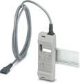 IFS-OP-CRADLE - The adapter (IFS-OP-CRADLE) for the operator interface is ideal for use as a remote operator panel and display device for 17.5 mm / 35 mm modules. Can be mounted directly on the DIN rail. Replacement part: 2905872 IFS-BT-PROG-ADAPTER.
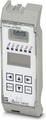 IFS-OP-UNIT, The control unit facilitates straightforward parameterization and operation of the MACX MCR(-EX)-...-UI(REL)(-UP) on-site, even without software. With the copying function, other modules can be configured quickly and cost-effectively. Can be snapped onto the 35 mm module.
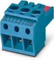 MACX MCR-EX-I20 - Connection terminal block for current signals +20 mA ...-20 mA for safe switching of limit values, in combination with MACX...EX-T-UI... temperature transducers.
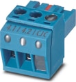 MACX MCR-EX-CJC - Plug for cold junction compensation for thermocouples, for safe switching of limit values, in combination with MACX ...EX-T-UI... temperature transducers.
Why Proax for Phoenix Contact 2924689?
Proax is an authorized distributor of Phoenix Contact 2924689 and one of Phoenix Contact's largest distributors in North America. Our highly skilled in-house technical team is ready to assist with any technical needs.
Have a question in mind? to help you get the right product as quickly as possible for your project. We're always here to help!
Short Lead Time
Highly Trained Staff
Live Chat
Technical Support
Local Inventory
60+ Years Experience
Additional Information
| Pack Size | 1 |
Recommended
 MACX MCR-EX-SL-IDSI-I, Ex i output signal conditioner, HART Isolates and sends intrinsically safe 0/4-20 mA signals to a load (I/P converters, control valves, displays) in Ex areas. Electrical 3-way isolation, wire break recognition, SIL 2 in accordance with IEC 61508.
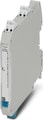 MACX MCR-EX-SL-IDSI-I-SP, Ex i output signal conditioner, HART. Isolates and sends intrinsically safe 0/4-20 mA signals to a load (I/P converters, control valves, displays) in Ex areas. Electrical 3-way isolation, wire break recognition, SIL 2 in accordance with IEC 61508, spring-cage connection.
 MACX MCR-EX-SL-NAM-2RO - Ex i NAMUR isolating amplifier For operating proximity sensors and switches in Ex areas. The signals are transmitted via 2 relay outputs (N/O contact) to the safe area. Line fault detection (LFD), 3-way isolation, SIL 2.
 MACX MCR-EX-SL-NAM-2RO-SP - Ex i NAMUR isolating amplifier For operating proximity sensors and switches in Ex areas. The signals are transmitted via 2 relay outputs (N/O contact) to the safe area. Line fault detection (LFD), 3-way isolation, SIL 2.
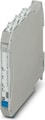 MACX MCR-EX-SL-NAM-2T - Ex i NAMUR isolating amplifier For operating proximity sensors and switches in Ex areas. The signals are transmitted via 2 transistor outputs (passive) to the safe area. Line fault detection (LFD), 3-way isolation, SIL 2.
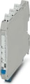 Ex i NAMUR isolating amplifier for operating proximity sensors and switches in the Ex area. The signals are transmitted via 2 transistor outputs (passive) to the safe area. Line fault detection (LFD), 3-way isolation, SIL 2.
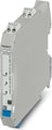 MACX MCR-EX-SL-NAM-HO - Ex i NAMUR signal conditioners. For operating Ex i proximity sensors and switches in hazardous areas. Passive transistor output (resistive, Honeywell-compatible), line fault transparency, up to SIL 2 according to IEC 61508; screw connection.
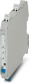 MACX MCR-EX-SL-NAM-HO-SP - Ex i NAMUR signal conditioners. For operating Ex i proximity sensors and switches in hazardous areas. Passive transistor output (resistive, Honeywell-compatible), line fault transparency, up to SIL 2 according to IEC 61508; Push-in connection.
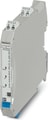 MACX MCR-EX-SL-NAM-NAM - Ex i NAMUR signal conditioner for operating Ex i proximity sensors and switches in the Ex area. Passive transistor output (resistive in accordance with EN 60947-5-6), line fault transparency, up to SIL 2 in accordance with IEC 61508, screw connection
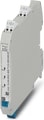 MACX MCR-EX-SL-NAM-NAM-SP - Ex i NAMUR signal conditioner for operating Ex i proximity sensors and switches in the Ex area. Passive transistor output (resistive in accordance with EN 60947-5-6), line fault transparency, up to SIL 2 in accordance with IEC 61508, Push-in connection
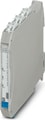 MACX MCR-EX-SL-NAM-R - Ex i NAMUR signal conditioner. For operating proximity sensors and switches in a potentially explosive area. The signals are transmitted by a relay output (changeover contact) to a safe area. Line fault detection (LFD), 3-way isolation, SIL 2.
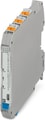 MACX MCR-EX-SL-NAM-R-SP - Ex i NAMUR signal conditioner. For operating proximity sensors and switches in a potentially explosive area. The signals are transmitted by a relay output (changeover contact) to a safe area. Line fault detection (LFD), 3-way isolation, SIL 2.
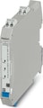 MACX MCR-EX-SL-NAM-YO - Ex i NAMUR signal conditioners. For operating Ex i proximity sensors and switches in hazardous areas. Passive transistor output (resistive, Yokogawa-compatible), line fault transparency, up to SIL 2 according to IEC 61508; screw connection.
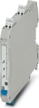 MACX MCR-EX-SL-NAM-YO-SP - Ex i NAMUR signal conditioners. For operating Ex i proximity sensors and switches in hazardous areas. Passive transistor output (resistive, Yokogawa-compatible), line fault transparency, up to SIL 2 according to IEC 61508; Push-in connection