Featured
2904600
SKU
PHX2904600
MPN
QUINT4-PS/1AC/24DC/5
Series QUINT4-PS
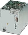
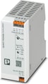
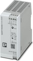
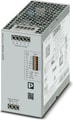
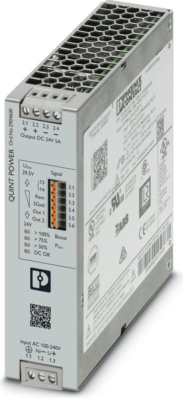
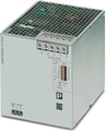
QUINT4-PS/1AC/24DC/5 - Power supply unit
Primary-switched QUINT POWER power supply with free choice of output characteristic curve, SFB (selective fuse breaking) technology, and NFC interface, input: 1-phase, output: 24 V DC/5 A
- SFB technology trips standard circuit breakers selectively, loads that are connected in parallel continue working
- Preventive function monitoring indicates critical operating states before errors occur
- Signaling thresholds and characteristic curves that can be adjusted via NFC maximize system availability
- Easy system extension thanks to static boost; starting of difficult loads thanks to dynamic boost
- High degree of immunity, thanks to integrated gas-filled surge arrester and mains failure bridging time of more than 20 milliseconds
- Robust design thanks to metal housing and wide temperature range from -40°C to +70°C
- Worldwide use thanks to the wide range input and international approval package
QUINT4-PS
The Phoenix Contact QUINT4-PS Series represents the fourth generation of high-performance QUINT POWER power supplies, engineered to provide superior system availability and advanced functionality for demanding industrial applications. These power supplies are designed for DIN rail mounting and offer a range of innovative features to ensure reliable and efficient operation.
Key Features:
SFB (Selective Fuse Breaking) Technology: Delivers up to six times the nominal current for 15 milliseconds, enabling standard circuit breakers to trip selectively. This ensures that only the faulty circuit is disconnected, while critical system components continue to operate without interruption.
NFC Interface: Allows for the customization of signaling thresholds and characteristic curves via Near Field Communication (NFC). This feature enables easy configuration and adaptation to specific application requirements.
Preventive Function Monitoring: Continuously monitors critical operating parameters and provides early warning signals before faults occur. This proactive approach facilitates timely maintenance and reduces the risk of unexpected system downtime.
Dynamic Boost and Static Boost: Offers power reserves with Dynamic Boost providing up to 200% of the nominal current for short durations (5 seconds) to start heavy loads, and Static Boost providing up to 125% of the nominal current continuously for reliable operation of high-demand applications.
Technical Specifications
Input data
| Control input (configurable) Rem | Output power ON/OFF (SLEEP MODE) |
| Default | Output power ON (>40 kΩ/24 V DC/open bridge between Rem and SGnd) |
AC operation
| Supply system configuration | Star network |
| Nominal input voltage range | 100 V AC ... 240 V AC |
| Input voltage range | 100 V AC ... 240 V AC -15 % ... +10 % |
| Derating | < 100 V AC (1 %/V) |
| Electric strength, max. | 300 V AC 60 s |
| Typical national grid voltage | 120 V AC |
| Typical national grid voltage | 230 V AC |
| Voltage type of supply voltage | AC |
| Inrush Current | typ. 14 A (at 25 °C) |
| Inrush current integral (I2t) | < 0.3 A2s |
| Inrush current limitation | 14 A (after 1 ms) |
| AC frequency range | 50 Hz ... 60 Hz -10 % ... +10 % |
| Frequency range (fN) | 50 Hz ... 60 Hz -10 % ... +10 % |
| Frequency range (fN) | 16.7 Hz (acc. to EN 50163) |
| Mains buffering time | typ. 28 ms (120 V AC) |
| Mains buffering time | typ. 38 ms (230 V AC) |
| Current consumption | 1.7 A (100 V AC) |
| Current consumption | 1.5 A (120 V AC) |
| Current consumption | 0.9 A (230 V AC) |
| Current consumption | 0.8 A (240 V AC) |
| Nominal Power Consumption | 163 VA |
| Protective circuit | Transient surge protection; Varistor, gas-filled surge arrester |
| Power factor (cos phi) | 0.82 |
| Switch-on time | < 500 ms |
| Typical response time | 300 ms (from SLEEP MODE) |
| Input fuse | 6.3 A (slow-blow, internal) |
| Recommended breaker for input protection | 6 A ... 16 A (Characteristic B, C, D, K or comparable) |
| Discharge current to PE | < 3.5 mA |
| Discharge current to PE | 1.1 mA (264 V AC, 60 Hz) |
DC operation
| Nominal input voltage range | 110 V DC ... 250 V DC |
| Input voltage range | 110 V DC ... 250 V DC -18 % ... +40 % |
| Derating | < 110 V DC (1 %/V) |
| Voltage type of supply voltage | DC |
| Current consumption | 1.6 A (110 V DC) |
| Current consumption | 0.7 A (250 V DC) |
Output data
| Efficiency | typ. 88.8 % (120 V AC) |
| Efficiency | typ. 89.2 % (230 V AC) |
| Output characteristic | U/I Advanced |
| Output characteristic | Smart HICCUP |
| Output characteristic | FUSE MODE |
| Nominal Output Voltage | 24 V DC |
| Setting range of the output voltage (USet) | 24 V DC ... 29.5 V DC (constant capacity) |
| Nominal output current (IN) | 5 A |
| Static Boost (IStat.Boost) | 6.25 A |
| Dynamic Boost (IDyn.Boost) | 10 A (5 s) |
| Selective Fuse Breaking (ISFB) | 30 A (15 ms) |
| Magnetic circuit breaker tripping | A1 ... A4 / B2 / C1 ... C2 / Z1 ... Z4 |
| Derating | > 60 °C ... 70 °C (2.5 %/K) |
| Feedback voltage resistance | ≤ 35 V DC |
| Protection against overvoltage at the output (OVP) | ≤ 32 V DC |
| Control deviation | < 0.5 % (Static load change 10 % ... 90 %) |
| Control deviation | < 4 % (Dynamic load change 10 % ... 90 %, (10 Hz)) |
| Control deviation | < 0.25 % (change in input voltage ±10 %) |
| Residual ripple | < 30 mVPP (with nominal values) |
| Short-circuit-proof | yes |
| No-load proof | yes |
| Output Power | 120 W |
| Output Power | 150 W |
| Output Power | 240 W |
| Apparent power | 180 VA (120 V, UOUT = 24 V, IOUT = stat. Boost) |
| Apparent power | 198 VA (230 V, UOUT = 24 V, IOUT = stat. Boost) |
| Maximum no-load power dissipation | < 3 W (120 V AC) |
| Maximum no-load power dissipation | < 3 W (230 V AC) |
| Power loss nominal load max. | < 17 W (120 V AC) |
| Power loss nominal load max. | < 16 W (230 V AC) |
| Power dissipation SLEEP MODE | < 3 W (120 V AC) |
| Power dissipation SLEEP MODE | < 3 W (230 V AC) |
| Crest factor | typ. 1.55 (120 V AC) |
| Crest factor | typ. 1.78 (230 V AC) |
| Rise time | 50 ms (UOut = 10 % ... 90 %) |
| Connection in parallel | yes, for redundancy and increased capacity |
| Connection in series | yes |
Signal
| Signal ground SGnd | Reference potential for Out1, Out2, and Rem |
Signal Out 1 (configurable)
| Digital | 24 V DC 20 mA |
| Default | 24 V DC 20 mA 24 V DC for UOut > 0.9 x USet |
Signal Out 2 (configurable)
| Digital | 24 V DC 20 mA |
| Analog | 4 mA ... 20 mA ±5 % (Load ≤400 Ω) |
| Default | 24 V DC 20 mA 24 V DC for POut < PN |
Signal relay 13/14 (configurable)
| Default | closed (Uout > 0.9 USet) |
| Digital | 24 V DC 1 A |
| Digital | 30 V AC/DC 0.5 A |
Input
| Connection Method | Screw connection |
| Conductor cross section, rigid min. | 0.2 mm² |
| Conductor cross section, rigid max. | 2.5 mm² |
| Conductor cross section flexible min. | 0.2 mm² |
| Conductor cross section flexible max. | 2.5 mm² |
| Single conductor/flexible terminal point with ferrule with plastic sleeve, min. | 0.25 mm² |
| Single conductor/flexible terminal point with ferrule with plastic sleeve, max. | 2.5 mm² |
| Single conductor/flexible terminal point with ferrule without plastic sleeve, min. | 0.25 mm² |
| Single conductor/flexible terminal point with ferrule without plastic sleeve, max. | 2.5 mm² |
| Conductor cross section AWG min. | 24 |
| Conductor cross section AWG max. | 14 |
| Stripping length | 6.5 mm |
| Tightening torque, min | 0.5 Nm |
| Tightening torque max | 0.6 Nm |
Output
| Connection Method | Screw connection |
| Conductor cross section, rigid min. | 0.2 mm² |
| Conductor cross section, rigid max. | 2.5 mm² |
| Conductor cross section flexible min. | 0.2 mm² |
| Conductor cross section flexible max. | 2.5 mm² |
| Single conductor/flexible terminal point with ferrule with plastic sleeve, min. | 0.25 mm² |
| Single conductor/flexible terminal point with ferrule with plastic sleeve, max. | 2.5 mm² |
| Single conductor/flexible terminal point with ferrule without plastic sleeve, min. | 0.25 mm² |
| Single conductor/flexible terminal point with ferrule without plastic sleeve, max. | 2.5 mm² |
| Conductor cross section AWG min. | 24 |
| Conductor cross section AWG max. | 14 |
| Stripping length | 6.5 mm |
| Tightening torque, min | 0.5 Nm |
| Tightening torque max | 0.6 Nm |
Signal
| Connection Method | Push-in connection |
| Conductor cross section, rigid min. | 0.2 mm² |
| Conductor cross section, rigid max. | 1 mm² |
| Conductor cross section flexible min. | 0.2 mm² |
| Conductor cross section flexible max. | 1.5 mm² |
| Single conductor/flexible terminal point with ferrule with plastic sleeve, min. | 0.2 mm² |
| Single conductor/flexible terminal point with ferrule with plastic sleeve, max. | 0.75 mm² |
| Single conductor/flexible terminal point with ferrule without plastic sleeve, min. | 0.2 mm² |
| Single conductor/flexible terminal point with ferrule without plastic sleeve, max. | 1.5 mm² |
| Conductor cross section AWG min. | 24 |
| Conductor cross section AWG max. | 16 |
| Stripping length | 8 mm |
Signaling
| Types of signaling | LED |
| Types of signaling | Floating signal contact |
| Types of signaling | Active signal output Out1 (digital, configurable) |
| Types of signaling | Active signal output Out2 (analog, configurable) |
| Types of signaling | Remote contact |
| Types of signaling | Signal ground SGnd |
Signal output
| POut | > 100 % (LED lights up yellow, output power > 120 W) |
| POut | > 75 % (LED lights up green, output power > 90 W) |
| POut | > 50 % (LED lights up green, output power > 60 W) |
| UOut | > 0.9 x USet (LED lights up green) |
| UOut | < 0.9 x USet (LED flashes green) |
Electrical properties
| Number of phases | 1.00 |
| Insulation voltage input/output | 4 kV AC (type test) |
| Insulation voltage input/output | 2 kV AC (routine test) |
| Insulation voltage output / PE | 0.5 kV DC (type test) |
| Insulation voltage output / PE | 0.5 kV DC (routine test) |
| Insulation voltage input / PE | 3.5 kV AC (type test) |
| Insulation voltage input / PE | 2.4 kV AC (routine test) |
| Switching frequency | 90.00 kHz ... 110.00 kHz (Auxiliary converter stage) |
| Switching frequency | 50.00 kHz ... 235.00 kHz (Main converter stage) |
| Switching frequency | 55.00 kHz ... 625.00 kHz (PFC stage) |
Product properties
| Product family | QUINT POWER |
| MTBF (IEC 61709, SN 29500) | > 1532000 h (25 °C) |
| MTBF (IEC 61709, SN 29500) | > 930000 h (40 °C) |
| MTBF (IEC 61709, SN 29500) | > 431000 h (60 °C) |
| Environmental protection directive | RoHS Directive 2011/65/EU |
| Environmental protection directive | WEEE |
| Environmental protection directive | Reach |
Insulation characteristics
| Protection class | I |
| Degree of pollution | 2 |
Life expectancy (electrolytic capacitors)
| Current | 2.5 A |
| Temperature | 40 °C |
| Time | 184000 h |
| Additional text | 120 V AC |
| Current | 2.5 A |
| Temperature | 40 °C |
| Time | 183000 h |
| Additional text | 230 V AC |
| Current | 5 A |
| Temperature | 25 °C |
| Time | 224000 h |
| Additional text | 120 V AC |
| Current | 5 A |
| Temperature | 25 °C |
| Time | 259000 h |
| Additional text | 230 V AC |
| Current | 5 A |
| Temperature | 40 °C |
| Time | 79000 h |
| Additional text | 120 V AC |
| Current | 5 A |
| Temperature | 40 °C |
| Time | 91000 h |
| Additional text | 230 V AC |
Dimensions
| Width | 36 mm |
| Height | 130 mm |
| Depth | 125 mm |
Installation dimensions
| Installation distance right/left | 5 mm / 5 mm |
| Installation distance top/bottom | 50 mm / 50 mm |
Alternative assembly
| Width | 122 mm |
| Height | 130 mm |
| Depth | 39 mm |
Mounting
| Mounting Type | DIN rail mounting |
| Assembly instructions | alignable: PN ≥50%, 5 mm horizontally, 15 mm next to active components, 50 mm verticallyalignable: PN <50%, 0 mm horizontally, 40 mm vertically top, 20 mm vertically bottom |
| Mounting Position | horizontal DIN rail NS 35, EN 60715 |
| With protective coating | No |
Material specifications
| Flammability rating according to UL 94 (housing / terminal blocks) | V0 |
| Housing Material | Metal |
| Hood version | Stainless steel X6Cr17 |
| Side element version | Aluminum |
Ambient conditions
| Degree of Protection | IP20 |
| Ambient Temperature (Operation) | -25 °C ... 70 °C (> 60 °C Derating: 2,5 %/K) |
| Ambient temperature (storage/transport) | -40 °C ... 85 °C |
| Ambient temperature (start-up type tested) | -40 °C |
| Maximum altitude | ≤ 5000 m (> 2000 m, observe derating) |
| Climatic class | 3K3 (in acc. with EN 60721) |
| Max. permissible relative humidity (operation) | ≤ 95 % (at 25 °C, non-condensing) |
| Shock | 18 ms, 30g, in each space direction (according to IEC 60068-2-27) |
| Vibration (Operation) | 5 Hz ... 100 Hz resonance search 2.3g, 90 min., resonance frequency 2.3g, 90 min. (according to DNV GL Class C) |
Standards and Regulations
| Rail applications | EN 50121-3-2 |
| Rail applications | EN 50121-4 |
| Rail applications | EN 50121-5 |
| Rail applications | EN 50163 |
| Rail applications | IEC 62236-3-2 |
| Rail applications | IEC 62236-4 |
| Rail applications | IEC 62236-5 |
| HART FSK Physical Layer Test Specification Compliance | Output voltage UOut compliant |
| Standard – Limitation of mains harmonic currents | EN 61000-3-2 |
| Standard - Electrical safety | IEC 61010-2-201 (SELV) |
| Standard – Safety extra-low voltage | IEC 61010-1 (SELV) |
| Standard – Safety extra-low voltage | IEC 61010-2-201 (PELV) |
| Standard - Safe isolation | IEC 61558-2-16 |
| Standard - Safe isolation | IEC 61010-2-201 |
| Standard - safety for equipment for measurement, control, and laboratory use | IEC 61010-1 |
| Standard - Safety of transformers | EN 61558-2-16 |
| Standard - power supply devices for low voltage with DC output | EN 61204-3 |
| Battery charging | DIN 41773-1 |
| Approval - requirement of the semiconductor industry with regard to mains voltage dips | SEMI F47-0706, EN 61000-4-11 |
Overvoltage category
| EN 61010-1 | II (≤ 5000 m) |
| EN 62477-1 | III (≤ 2000 m) |
Approvals
| CSA | CAN/CSA-C22.2 No. 60950-1-07 |
| CSA | CSA-C22.2 No. 107.1-01 |
| Shipbuilding approval | DNV GL, PRS, BV, LR, ABS |
| SIQ | BG (type approved) |
| UL approvals | UL Listed UL 508 |
| UL approvals | UL/C-UL Recognized UL 60950-1 |
| UL approvals | UL ANSI/ISA-12.12.01 Class I, Division 2, Groups A, B, C, D (Hazardous Location) |
EMC data
| Low Voltage Directive | Conformance with Low Voltage Directive 2014/35/EC |
| EMC requirements for noise emission | EN 61000-6-3 |
| EMC requirements for noise emission | EN 61000-6-4 |
| EMC requirements for noise immunity | EN 61000-6-1 |
| EMC requirements for noise immunity | EN 61000-6-2 |
| Electromagnetic compatibility | Conformance with EMC Directive 2014/30/EU |
| EMC requirements, power plant | IEC 61850-3 |
| EMC requirements, power plant | EN 61000-6-5 |
| Conducted noise emission | EN 55016 |
| Conducted noise emission | EN 61000-6-3 (Class B) |
| Noise emission | Additional basic standard EN 61000-6-5 (immunity in power station), IEC/EN 61850-3 (energy supply) |
| Noise emission | EN 55016 |
| Noise emission | EN 61000-6-3 (Class B) |
| DNV GL conducted interference | Class A |
| Additional text | Area power distribution |
| DNV GL noise radiation | Class B |
| Additional text | Bridge and deck area |
Harmonic currents
| Standards/regulations | EN 61000-3-2 |
| Standards/regulations | EN 61000-3-2 (Class A) |
| Frequency Range | 0 kHz ... 2 kHz |
Flicker
| Standards/regulations | EN 61000-3-3 |
| Standards/regulations | EN 61000-3-3 |
| Frequency Range | 0 kHz ... 2 kHz |
Electrostatic discharge
| Standards/regulations | EN 61000-4-2 |
| Contact discharge | 8 kV (Test Level 4) |
| Discharge in air | 15 kV (Test Level 4) |
| Comments | Criterion A |
Electromagnetic HF field
| Standards/regulations | EN 61000-4-3 |
| Frequency Range | 80 MHz ... 1 GHz |
| Test field strength | 20 V/m (Test Level 3) |
| Frequency Range | 1 GHz ... 6 GHz |
| Test field strength | 10 V/m (Test Level 3) |
| Frequency Range | 1 GHz ... 6 GHz |
| Test field strength | 10 V/m (Test Level 3) |
| Comments | Criterion A |
Fast transients (burst)
| Standards/regulations | EN 61000-4-4 |
| Input | 4 kV (Test Level 4 - asymmetrical) |
| Output | 4 kV (Test Level 4 - asymmetrical) |
| Signal | 4 kV (Test Level 4 - asymmetrical) |
| Comments | Criterion A |
Surge voltage load (surge)
| Standards/regulations | EN 61000-4-5 |
| Input | 3 kV (Test Level 4 - symmetrical) |
| Input | 6 kV (Test Level 4 - asymmetrical) |
| Output | 1 kV (Test Level 3 - symmetrical) |
| Output | 2 kV (Test Level 3 - asymmetrical) |
| Signal | 1 kV (Test Level 2 - asymmetrical) |
| Comments | Criterion A |
Conducted interference
| Standards/regulations | EN 61000-4-6 |
| I/O/S | asymmetrical |
| Frequency Range | 0.15 MHz ... 80 MHz |
| Comments | Criterion A |
| Voltage | 10 V (Test Level 3) |
Power frequency magnetic field
| Standards/regulations | EN 61000-4-8 |
| Frequency | 16.7 Hz |
| Frequency | 50 Hz |
| Frequency | 60 Hz |
| Test field strength | 100 A/m |
| Additional text | 60 s |
| Comments | Criterion A |
| Frequency | 50 Hz |
| Frequency | 60 Hz |
| Frequency Range | 50 Hz ... 60 Hz |
| Test field strength | 1 kA/m |
| Additional text | 3 s |
| Frequency | 0 Hz |
| Test field strength | 300 A/m |
| Additional text | DC, 60 s |
Voltage dips
| Standards/regulations | EN 61000-4-11 |
| Voltage | 230 V AC |
| Frequency | 50 Hz |
| Voltage dip | 70 % |
| Number of periods | 0.5 / 1 / 25 periods |
| Additional text | Test Level 2 |
| Comments | Criterion A: 0.5 / 1 / 25 periods |
| Voltage dip | 40 % |
| Number of periods | 5 / 10 / 50 periods |
| Additional text | Test Level 2 |
| Comments | Criterion A |
| Voltage dip | 0 % |
| Number of periods | 0,5 / 1 / 5 / 50 / 250 periods |
| Additional text | Test Level 2 |
| Comments | Criterion A: 0.5 / 1 periodCriterion B: 5 / 50 / 250 periods |
Pulse-shape magnetic field
| Standards/regulations | EN 61000-4-9 |
| Test field strength | 1000 A/m |
| Comments | Criterion A |
Attenuated sinusoidal oscillations (ring wave)
| Standards/regulations | EN 61000-4-12 |
| Input | 2 kV (Test Level 4 - symmetrical) |
| Input | 4 kV (Test Level 4 - asymmetrical) |
| Comments | Criterion A |
Asymmetrical conducted disturbance variables
| Standards/regulations | EN 61000-4-16 |
| Test level 1 | 15 Hz 150 Hz (Test Level 4) |
| Voltage | 30 V 3 V |
| Test level 2 | 150 Hz 1.5 kHz (Test Level 4) |
| Voltage | 3 V |
| Test level 3 | 1.5 kHz 15 kHz (Test Level 4) |
| Voltage | 3 V 30 V |
| Test level 4 | 15 kHz 150 kHz (Test Level 4) |
| Voltage | 30 V |
| Test level 5 | 16.7 Hz 50 Hz 60 Hz (Test Level 4) |
| Voltage | 30 V (Permanent) |
| Test level 6 | 16.7 Hz 50 Hz 60 Hz (Test Level 4) |
| Voltage | 300 V (1 s) |
| Comments | Criterion A |
Attenuated oscillating wave
| Standards/regulations | EN 61000-4-18 |
| Input, output (test level 1) | 100 kHz 1 MHz (Test Level 3 - symmetrical) |
| Voltage | 1 kV |
| Input, output (test level 2) | 10 MHz |
| Voltage | 1 kV |
| Input, output (test level 3) | 100 kHz 1 MHz (Test Level 3 - asymmetrical) |
| Voltage | 2.5 kV |
| Signals (test level 1) | 100 kHz 1 MHz (Test Level 3 - symmetrical) |
| Voltage | 1 kV |
| Signals (test level 2) | 100 kHz 1 MHz (Test Level 3 - asymmetrical) |
| Voltage | 2.5 kV |
| Comments | Criterion A |
Attenuated oscillating magnetic field
| Standards/regulations | EN 61000-4-10 |
| Test field strength | 110 A/m |
| Test level 1 | 100 kHz |
| Test field strength | 110 A/m |
| Test level 2 | 1 MHz |
| Comments | Criterion A |
Criteria
| Criterion A | Normal operating behavior within the specified limits. |
| Criterion B | Temporary impairment to operational behavior that is corrected by the device itself. |
| Criterion C | Temporary adverse effects on the operating behavior, which the device corrects automatically or which can be restored by actuating the operating elements. |
Accessories

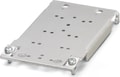
 UWA 182/52 - Universal wall adapter for securely mounting the device in the event of strong vibrations. The device is screwed directly onto the mounting surface. The universal wall adapter is attached on the top/bottom.
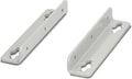 UWA 130 - 2-piece universal wall adapter for securely mounting the device in the event of strong vibrations. The profiles that are screwed onto the side of the device are screwed directly onto the mounting surface. The universal wall adapter is attached on the left/right.
 PLT-SEC-T3-230-FM-UT - Type 2/3 surge protection, consisting of protective plug and base element with screw connection. For single-phase power supply network with integrated status indicator and remote signaling. Nominal voltage: 230 V AC/DC
 PLT-SEC-T3-24-FM-UT - Type 3 surge protection, consisting of protective plug and base element, with integrated status indicator and remote signaling for single-phase power supply networks. Nominal voltage: 24 V AC/DC
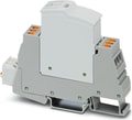 PLT-SEC-T3-230-FM-PT - Type 2/3 surge protection, consisting of protective plug and base element with Push-in connection. For single-phase power supply network with integrated status indicator and remote signaling. Nominal voltage: 230 V AC/DC
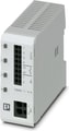 CBMC E4 24DC/1-4A NO - Multi-channel electronic circuit breaker for protecting four loads at 24 V DC in the event of overload and short circuit. With electronic locking of the set nominal currents. For installation on DIN rails.
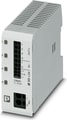 CBMC E4 24DC/1-4A+ IOL - Multi-channel electronic circuit breaker with IO-Link interface for protecting four loads at 24 V DC in the event of overload and short circuit. With electronic locking of the set nominal currents. For installation on DIN rails.

Why Proax for Phoenix Contact 2904600?
Proax is an authorized distributor of Phoenix Contact 2904600 and one of Phoenix Contact's largest distributors in North America. Our highly skilled in-house technical team is ready to assist with any technical needs.
Have a question in mind? to help you get the right product as quickly as possible for your project. We're always here to help!
Short Lead Time
Highly Trained Staff
Live Chat
Technical Support
Local Inventory
60+ Years Experience
Additional Information
| Pack Size | 1 |
Recommended
 QUINT4-PS/1AC/24DC/40 - Primary-switched QUINT POWER power supply with free choice of output characteristic curve, SFB (selective fuse breaking) technology, and NFC interface, input: 1-phase, output: 24 V DC/40 A
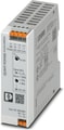 QUINT4-PS/1AC/24DC/2.5/PT - Primary-switched power supply unit QUINT POWER, Push-in connection, DIN rail mounting, input: 1-phase, output: 24 V DC / 2.5 A
 QUINT4-PS/1AC/24DC/2.5/SC - Primary-switched power supply unit QUINT POWER, Screw connection, DIN rail mounting, input: 1-phase, output: 24 V DC / 2.5 A. Alternative item: 2909576
 QUINT4-PS/1AC/24DC/10 - Primary-switched QUINT POWER power supply with free choice of output characteristic curve, SFB (selective fuse breaking) technology, and NFC interface, input: 1-phase, output: 24 V DC/10 A
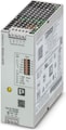 Primary-switched QUINT POWER supply for DIN rail mounting, with selectable output characteristic curve and SFB (Selective Fuse Breaking) Technology, protective coating and integrated decoupling MOSFET, input: 1-phase, output: 24 V DC / 10 A
 QUINT4-PS/1AC/24DC/1.3/SC - Primary-switched power supply unit QUINT POWER, Screw connection, DIN rail mounting, input: 1-phase, output: 24 V DC / 1.3 A
 QUINT4-PS/1AC/24DC/1.3/PT - Primary-switched power supply unit QUINT POWER, Push-in connection, DIN rail mounting, input: 1-phase, output: 24 V DC / 1.3 A
 QUINT4-PS/1AC/12DC/7.5/PT - Primary-switched power supply unit QUINT POWER, Push-in connection, DIN rail mounting, input: 1-phase, output: 12 V DC / 7.5 A
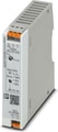 QUINT4-PS/1AC/12DC/2.5/PT - Primary-switched power supply unit QUINT POWER, Push-in connection, DIN rail mounting, input: 1-phase, output: 12 V DC / 2.5 A
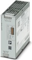 QUINT4-PS/1AC/12DC/15 - Primary-switched QUINT POWER power supply with free choice of output characteristic curve, SFB (Selective Fuse Breaking) Technology, and NFC interface, input: 1-phase, output: 12 V DC / 15 A
 QUINT4-PS/1AC/110DC/4 - Primary-switched power supply unit QUINT POWER, Screw connection, DIN rail mounting, input: 1-phase, output: 110 V DC / 4 A
 QUINT4-PS/1AC/48DC/5 - Primary-switched QUINT POWER power supply for DIN rail mounting with free choice of output characteristic curve and SFB (Selective Fuse Breaking) technology, input: 1-phase, output: 48 V DC / 5 A
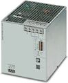 QUINT POWER primary-switched power supply with free choice of output characteristic curve, SFB (Selective Fuse Breaking) Technology, and NFC interface, input: 1-phase, output: 48 V DC/20 A
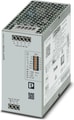 QUINT4-PS/1AC/48DC/10 - Primary-switched QUINT POWER power supply for DIN rail mounting with free choice of output characteristic curve and SFB (Selective Fuse Breaking) technology, input: 1-phase, output: 48 V DC / 10 A