








































2907753
 Official Distributor
SKU
PHX2907753
MPN
QUINT4-S-ORING/12-24DC/1X40/+
Weight
0.472 kg
Series QUINT4-S-ORING
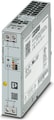
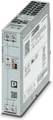
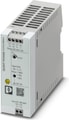
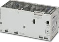
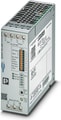
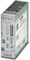
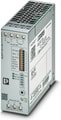
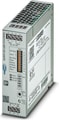
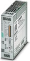
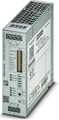
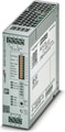
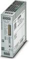
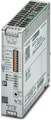
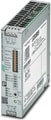
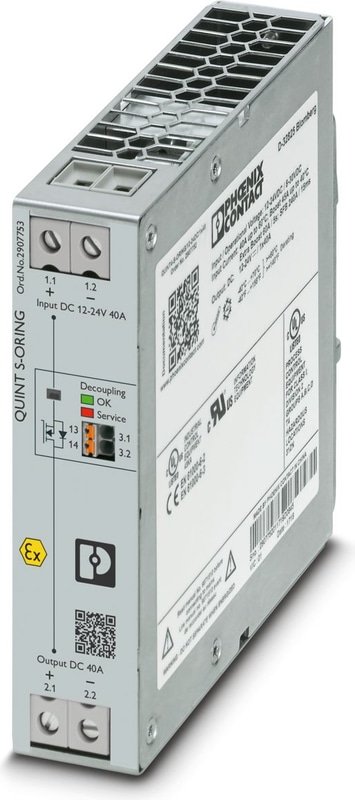
QUINT4-S-ORING/12-24DC/1X40/+ - Redundancy module, with protective coating
Active QUINT single redundancy module for DIN rail mounting, protective coating, input: 12 V DC ... 24 V DC, output: 12 V DC ... 24 V DC / 1 x 40 A, integrated surge protection <28.8 V DC, incl. mounted UTA 107/30 universal DIN rail adapter
- Consistent redundancy up to the load
- Input voltage and decoupling section monitored on a permanent basis
- Save energy by decoupling with MOSFET
- Protection against surge voltages in excess of 30 V DC at the output
Documents
Technical Specifications
DC operation
| Nominal input voltage range | 12 V DC ... 24 V DC |
| Input voltage range | 8 V DC ... 26 V DC (SELV) |
| Typical national grid voltage | 12 V DC |
| Typical national grid voltage | 24 V DC |
| Voltage type of supply voltage | DC |
| Current consumption | 40 A |
| Static Boost (IStat.Boost) | 45 A |
| Dynamic Boost (IDyn.Boost) | 60 A (5 s) |
| Selective Fuse Breaking (ISFB) | 215 A (15 ms) |
| Reverse polarity protection | < yes60 V |
| Nominal input current (IN) | 40 A (-40 °C ... 60 °C) |
| Input current IStatic | 45 A (40 °C) |
| Input current IDynamic | 60 A (5 s) |
| Input current ISFB | 215 A (15 ms) |
| Transient surge protection | Varistor |
| Voltage drop, input/output | 0.1 V DC |
Output data
| Efficiency | typ. 99 % (12 V DC) |
| Efficiency | typ. 99.2 % (24 V DC) |
| Nominal Output Voltage | UIn - 0.1 V |
| Nominal output current (IN) | 40 A |
| Static Boost (IStat.Boost) | 45 A |
| Dynamic Boost (IDyn.Boost) | 60 A (5 s) |
| Selective Fuse Breaking (ISFB) | 215 A (15 ms) |
| Derating | 60 °C ... 70 °C (2.5 %/K) |
| Protection against overvoltage at the output (OVP) | < 28.8 V DC |
| Power loss nominal load max. | 6.5 W (IOUT = 40 A) |
| Power loss nominal load max. | 6 W (IOUT = 40 A) |
| Connection in series | no |
Signal: OK, 13/14
| Output description | Group contact |
| Maximum Switching Voltage | max. 30 V AC/DC |
| Maximum Inrush Current | ≤ 100 mA (short-circuit-proof) |
Signal relay 13/14
| Default | open |
| Default | closed |
| Default | open |
| Default | open |
Input
| Connection Method | Screw connection |
| Conductor cross section, rigid min. | 0.5 mm² |
| Conductor cross section, rigid max. | 16 mm² |
| Conductor cross section flexible min. | 0.5 mm² |
| Conductor cross section flexible max. | 16 mm² |
| Single conductor/flexible terminal point with ferrule with plastic sleeve, min. | 0.5 mm² |
| Single conductor/flexible terminal point with ferrule with plastic sleeve, max. | 16 mm² |
| Single conductor/flexible terminal point with ferrule without plastic sleeve, min. | 0.5 mm² |
| Single conductor/flexible terminal point with ferrule without plastic sleeve, max. | 16 mm² |
| Conductor cross section AWG min. | 20 |
| Conductor cross section AWG max. | 6 |
| Stripping length | 10 mm |
| Screw thread | M4 |
| Tightening torque, min | 1.2 Nm |
| Tightening torque max | 1.5 Nm |
Output
| Connection Method | Screw connection |
| Conductor cross section, rigid min. | 0.5 mm² |
| Conductor cross section, rigid max. | 16 mm² |
| Conductor cross section flexible min. | 0.5 mm² |
| Conductor cross section flexible max. | 16 mm² |
| Single conductor/flexible terminal point with ferrule with plastic sleeve, min. | 0.5 mm² |
| Single conductor/flexible terminal point with ferrule with plastic sleeve, max. | 16 mm² |
| Single conductor/flexible terminal point with ferrule without plastic sleeve, min. | 0.5 mm² |
| Single conductor/flexible terminal point with ferrule without plastic sleeve, max. | 16 mm² |
| Conductor cross section AWG min. | 20 |
| Conductor cross section AWG max. | 6 |
| Stripping length | 10 mm |
| Screw thread | M4 |
| Tightening torque, min | 1.2 Nm |
| Tightening torque max | 1.5 Nm |
Signal
| Connection Method | Push-in connection |
| Conductor cross section, rigid min. | 0.2 mm² |
| Conductor cross section, rigid max. | 1.5 mm² |
| Conductor cross section flexible min. | 0.2 mm² |
| Conductor cross section flexible max. | 1.5 mm² |
| Single conductor/flexible terminal point with ferrule with plastic sleeve, min. | 0.2 mm² |
| Single conductor/flexible terminal point with ferrule with plastic sleeve, max. | 0.75 mm² |
| Single conductor/flexible terminal point with ferrule without plastic sleeve, min. | 0.2 mm² |
| Single conductor/flexible terminal point with ferrule without plastic sleeve, max. | 1.5 mm² |
| Conductor cross section AWG min. | 24 |
| Conductor cross section AWG max. | 16 |
| Stripping length | 8 mm |
Signaling
| Types of signaling | Relay contact, floating, current limited |
Signal output: OK, 13/14
| UIn < 8 V DC | LED off, input voltage not present or short circuit at redundancy module output |
| UIn > 8 V DC | LED lights up green, input voltage present |
| UIn > 28.8 V DC | LED flashing red, OVP active - input voltage exceeds the permissible voltage value |
| Redundancy modul faulty | LED lights up red, redundancy module needs to be factory tested |
Electrical properties
| Insulation voltage input, output / housing | 500 V DC |
Product properties
| Product family | QUINT S-ORING |
| MTBF (IEC 61709, SN 29500) | > 13486000 h (25 °C) |
| MTBF (IEC 61709, SN 29500) | > 7314000 h (40 °C) |
| MTBF (IEC 61709, SN 29500) | > 3379000 h (60 °C) |
| LED | yes |
Insulation characteristics
| Protection class | III |
| Degree of pollution | 2 |
Life expectancy (electrolytic capacitors)
| Current | 40 A |
| Temperature | 40 °C |
| Time | 160000 h |
| Additional text | 12 V DC |
| Current | 40 A |
| Temperature | 40 °C |
| Time | 149000 h |
| Additional text | 24 V DC |
Dimensions
| Width | 32 mm |
| Height | 130 mm |
| Depth | 125 mm |
Installation dimensions
| Installation distance right/left | 0 mm / 0 mm |
| Installation distance top/bottom | 40 mm / 20 mm |
Alternative assembly
| Width | 122 mm |
| Height | 130 mm |
| Depth | 35 mm |
Mounting
| Mounting Type | DIN rail mounting |
| Assembly note | alignable: PN ≥50%, 5 mm horizontally, 15 mm next to active components, 50 mm verticallyalignable: PN <50%, 0 mm horizontally, 40 mm vertically top, 20 mm vertically bottom |
| Mounting Position | horizontal DIN rail NS 35, EN 60715 |
Material specifications
| Flammability rating according to UL 94 (housing / terminal blocks) | V0 |
| Housing Material | Metal |
| Housing Material | Aluminum / stainless steel |
| Type of housing | Aluminum (AlMg3) |
| Hood version | Galvanized sheet steel, free from chrome (VI) |
Ambient conditions
| Degree of Protection | IP20 |
| Ambient Temperature (Operation) | -40 °C ... 70 °C (> 60 °C Derating: 2,5 %/K) |
| Ambient temperature (storage/transport) | -40 °C ... 85 °C |
| Maximum altitude | ≤ 5000 m (> 2000 m, observe derating) |
| Climatic class | 3K22 (in accordance with EN 60721-3-3) |
| Max. permissible relative humidity (operation) | ≤ 100 % (at 25 °C, non-condensing) |
| Shock | 18 ms, 30g, in each space direction (according to IEC 60068-2-27) |
| Vibration (Operation) | < 15 Hz, amplitude ±2.5 mm (according to IEC 60068-2-6) |
| Vibration (Operation) | 15 Hz ... 150 Hz, 2.3g, 90 min. |
| Temp code | T4 (-25 ... +70 °C; > 60 °C, Derating: 2,5 %/K) |
Standards and Regulations
| Standard - Electrical safety | IEC 62368-1 (SELV) |
| Standard – Safety extra-low voltage | IEC 62368-1 (SELV) und EN 60204-1 (PELV) |
Fire protection in rail vehicles
| Standard designation | Fire protection in rail vehicles |
| Standards/specifications | EN 45545-2 (HL3) |
Approvals
| Shipbuilding approval | DNV |
| UL approvals | UL/C-UL listed UL 508 |
| UL approvals | UL/C-UL Recognized UL 60950-1 |
| UL approvals | UL 121201 & CSA C22.2 No. 213-17 Class I, Division 2, Groups A, B, C, D T4 (Hazardous Location) |
Conformity/Approvals
| ATEX | II 3 G Ex ec nC IIC T4 Gc |
| ATEX | SIQ 21 ATEX 183 X |
| IECEx | Ex ec nC IIC T4 Gc |
| IECEx | IECEx SIQ 21.0001X |
| Functional Safety in accordance with IEC 61508 | SIL3 in accordance with IEC 61508-1 (in combination with product 2904602 QUINT4-PS/1AC/24DC/20) |
EMC data
| Electromagnetic compatibility | Conformance with EMC Directive 2014/30/EU |
| Low Voltage Directive | Conformance with Low Voltage Directive 2014/35/EC |
| EMC requirements for noise emission | EN 61000-6-3 |
| EMC requirements for noise emission | EN 61000-6-4 |
| EMC requirements for noise immunity | EN 61000-6-1 |
| EMC requirements for noise immunity | EN 61000-6-2 |
| Conducted noise emission | EN 55016 |
| Conducted noise emission | EN 61000-6-3 (Class B) |
| Noise emission | Additional basic standard EN 61000-6-5 (immunity in power station) |
| Noise emission | EN 55016 |
| Noise emission | EN 61000-6-3 (Class B) |
| DNV GL conducted interference | Class A |
| Additional text | Area power distribution |
| DNV GL noise radiation | Class B |
| Additional text | Bridge and deck area |
Electrostatic discharge
| Standards/regulations | EN 61000-4-2 |
| Contact discharge | 8 kV (Test Level 4) |
| Discharge in air | 15 kV (Test Level 4) |
| Comments | Criterion A |
Electromagnetic HF field
| Standards/regulations | EN 61000-4-3 |
| Frequency Range | 80 MHz ... 1 GHz |
| Test field strength | 20 V/m (Test Level 3) |
| Frequency Range | 1 GHz ... 6 GHz |
| Test field strength | 10 V/m (Test Level 3) |
| Comments | Criterion A |
Fast transients (burst)
| Standards/regulations | EN 61000-4-4 |
| Input | 2 kV (Test Level 4 - asymmetrical) |
| Output | 2 kV (Test Level 4 - asymmetrical) |
| Signal | 2 kV (Test Level 4 - asymmetrical) |
| Comments | Criterion A |
Surge voltage load (surge)
| Standards/regulations | EN 61000-4-5 |
| Input | 0.5 kV (Test Level 1 - symmetrical) |
| Input | 0.5 kV (Test Level 1 - asymmetrical) |
| Output | 0.5 kV (Test Level 1 - symmetrical) |
| Output | 0.5 kV (Test Level 1 - asymmetrical) |
| Signal | 1 kV (Test Level 2 - asymmetrical) |
| Comments | Criterion B |
Conducted interference
| Standards/regulations | EN 61000-4-6 |
| I/O/S | asymmetrical |
| Frequency Range | 0.15 MHz ... 80 MHz |
| Comments | Criterion A |
| Voltage | 20 V (Test Level 3) |
Power frequency magnetic field
| Standards/regulations | EN 61000-4-8 |
| Frequency | 16.67 Hz |
| Frequency | 50 Hz |
| Frequency | 60 Hz |
| Test field strength | 30 A/m |
| Additional text | 60 s |
| Comments | Criterion A |
Criteria
| Criterion A | Normal operating behavior within the specified limits. |
| Criterion B | Temporary impairment to operational behavior that is corrected by the device itself. |
Accessories
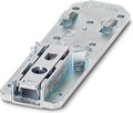
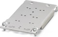
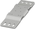 UWA 182/52 - Universal wall adapter for securely mounting the device in the event of strong vibrations. The device is screwed directly onto the mounting surface. The universal wall adapter is attached on the top/bottom.
Why Proax for Phoenix Contact 2907753?
Proax is an authorized distributor of Phoenix Contact 2907753 and one of Phoenix Contact's largest distributors in North America. Our highly skilled in-house technical team is ready to assist with any technical needs.
Have a question in mind? to help you get the right product as quickly as possible for your project. We're always here to help!
Short Lead Time
Highly Trained Staff
Live Chat
Technical Support
Local Inventory
60+ Years Experience
Additional Information
| Pack Size | 1 |
Recommended