2866611
 Official Distributor
SKU
PHX2866611
MPN
TRIO-UPS/1AC/24DC/ 5
Weight
1.109 kg
Series TRIO-UPS
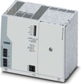
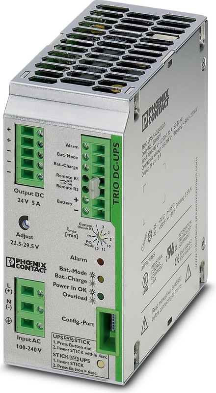
TRIO-UPS/1AC/24DC/ 5 - Uninterruptible power supply
Uninterruptible power supply with integrated power supply unit. For lead AGM battery module MINI-BAT/24/DC/1.3 AH, QUINT-BAT/24DC 3.4 AH … 12 AH nominal capacity. Input: 1-phase, output: 24 V DC/5 A. Screw connection technology
- Autonomous – in the event of AC mains failure the industrial PC continues operating without interruption
- Time-saving – when the supply voltage is restored, the industrial PC starts automatically
Technical Specifications
DC operation
| Input Voltage | 24 V DC |
| Nominal input voltage range | 100 V AC ... 240 V AC |
| Input voltage range | 85 V AC ... 264 V AC (Derating < 90 V AC: 2.5%V) |
| Input voltage range | 100 V DC ... 350 V DC (UL508: 100 ... 250 V) |
| Input Voltage Range AC | 85 V AC ... 264 V AC (Derating < 90 V AC: 2.5%V) |
| Input voltage range DC | 100 V DC ... 350 V DC (UL508: 100 ... 250 V) |
| Voltage type of supply voltage | AC/DC |
| Inrush Current | < 44 A (< 1.3 A2s) |
| Inrush current integral (I2t) | < 1.3 A2s |
| AC frequency range | 45 Hz ... 65 Hz |
| Frequency range DC | 0 Hz |
| Mains buffering time | see diagram |
| Buffer period | 20 min. (5 A) |
| Rotary selector switch | adjustable: 0.5 min; 1 min; 2 min; 3 min; 5 min; 10 min; 15 min; 20 min; PC-Mode |
| Current consumption | 0.95 A (230 V AC) |
| Current consumption | 1.1 A (230 V AC, maximum) |
| Current consumption | 1.7 A (120 V AC) |
| Current consumption | 1.8 A (120 V AC, maximum) |
| Protective circuit | Transient surge protection; Varistor |
| Power factor (cos phi) | approx. 0.5 |
| Typical response time | 150 ms (230 V AC) |
| Typical response time | 200 ms (120 V AC) |
| Input fuse | 6.3 A (slow-blow, internal) |
| Permissible backup fuse | B6 B10 B16 |
| Recommended breaker for input protection | 6 A ... 16 A (Characteristics B, C, D, K) |
Output data
| Efficiency | > 88 % (230 V AC, network operation) |
| Efficiency | > 86 % (120 V AC, network operation) |
| Efficiency | > 86 % (Battery operation) |
| Nominal Output Voltage | 24 V DC |
| Setting range of the output voltage (USet) | 22.5 V DC ... 29.5 V DC (Network operation; in the buffer mode, dependent on the battery voltage of 27.9 V DC ... 19.2 V DC) |
| Nominal output current (IN) | 5 A (-25 °C ... 55 °C) |
| Output current limit | max. 6 A (Mains operation) |
| Bridging time | 3600 s |
| Derating | 55 °C ... 70 °C (2.5 %/K) |
| Feedback voltage resistance | 35 V DC |
| Protection against overvoltage at the output (OVP) | < 35 V DC |
| Control deviation | < 1 % (change in load, static 10 % ... 90 %) |
| Residual ripple | < 10 mVPP |
| Output Power | 120 W |
| Nominal power | 120 W |
| Peak switching voltages nominal load | < 25 mVPP |
| Maximum no-load power dissipation | 2 W |
| Power loss nominal load max. | 16 W (230 V AC) |
| Power loss nominal load max. | 20 W (120 V AC) |
| Power dissipation battery operation | 4 W |
| Rise time | < 100 ms |
| Connection in parallel | yes, 2 |
| Connection in series | No |
Mains operation
| Nominal Output Voltage | 24 V DC |
| Output voltage range | 22.5 V DC ... 29.5 V DC |
| Nominal output current (IN) | 5 A |
Battery operation
| Nominal Output Voltage | 24 V DC |
| Output voltage range | 19.2 V DC ... 27.6 V DC (UOUT = UBAT - 0,5 V DC) |
| Nominal output current (IN) | 5 A |
Signal
| Output Voltage | + 24 V |
Signal: Alarm
| Output description | Transistor switching output |
| Maximum Switching Voltage | ≤ 24 V |
| Output Voltage | 24 V |
| Continuous load current | ≤ 200 mA |
Signal: Battery charge
| Output description | Transistor switching output |
| Maximum Switching Voltage | ≤ 24 V |
| Output Voltage | 24 V |
| Continuous load current | ≤ 200 mA |
Signal: Battery mode
| Output description | Transistor switching output |
| Maximum Switching Voltage | ≤ 24 V |
| Output Voltage | 24 V |
| Continuous load current | ≤ 200 mA |
Energy storage
| End-of-charge voltage | 25 V DC ... 30 V DC (Default 27.6 V DC) |
| Charging current | 1.5 A |
| Deep discharge protection | 18 V DC ... 21 V DC (Default 19.2 V DC) |
| Memory medium | external, battery 1.3 Ah / 3.4 Ah / 7.2 Ah / 12 Ah |
| Battery presence check/time interval | 60 s |
| Quality check of battery | 4 h ... 200 h (Default 12 h) |
| Charge characteristic curve | I/U characteristic curve |
| IQ Technology | no |
| Temperature compensation | 0 mV/K ... 200 mV/K (42 mV/K by default) |
| Alarm signaling threshold | 18 V DC ... 30 V DC (Default 20.4 V DC) |
| Network management | No |
Input
| Connection Method | Screw connection |
| Conductor cross section, rigid min. | 0.2 mm² |
| Conductor cross section, rigid max. | 2.5 mm² |
| Conductor cross section flexible min. | 0.2 mm² |
| Conductor cross section flexible max. | 2.5 mm² |
| Conductor cross section AWG min. | 24 |
| Conductor cross section AWG max. | 12 |
| Screw thread | M3 |
| Tightening torque, min | 0.5 Nm |
| Tightening torque max | 0.6 Nm |
Output
| Connection Method | Screw connection |
| Conductor cross section, rigid min. | 0.2 mm² |
| Conductor cross section, rigid max. | 2.5 mm² |
| Conductor cross section flexible min. | 0.2 mm² |
| Conductor cross section flexible max. | 2.5 mm² |
| Conductor cross section AWG min. | 24 |
| Conductor cross section AWG max. | 12 |
| Stripping length | 8 mm |
| Screw thread | M3 |
| Tightening torque, min | 0.5 Nm |
| Tightening torque max | 0.6 Nm |
Signal
| Conductor cross section, rigid min. | 0.2 mm² |
| Conductor cross section, rigid max. | 2.5 mm² |
| Conductor cross section flexible min. | 0.2 mm² |
| Conductor cross section flexible max. | 2.5 mm² |
| Conductor cross section AWG min. | 24 |
| Conductor cross section AWG max. | 12 |
| Screw thread | M3 |
| Tightening torque, min | 0.5 Nm |
| Tightening torque max | 0.6 Nm |
Interfaces
| Interface | IFS (Interface system data port) |
Signaling
| Types of signaling | LED |
Signal output
| Status display | Green LED |
| Note on status display | Mains voltage OK: Green LED, static at |
Signal output: Alarm
| Status display | Alarm |
| Note on status display | Red LED, static at |
Signal output: Battery charge
| Status display | Battery (battery charge) is being charged |
| Note on status display | Yellow LED, flashing |
Signal output: Battery mode
| Status display | Battery operation (Battery Mode) |
| Note on status display | LED yellow, static at |
Electrical properties
| Insulation voltage input/output | 4 kV (type test) |
| Insulation voltage input/output | 2 kV (routine test) |
| Insulation voltage output / PE | 500 V DC (routine test) |
| Insulation voltage input / PE | 2 kV AC (type test) |
| Insulation voltage input / PE | 2 kV AC (routine test) |
Product properties
| IQ Technology | no |
| MTBF (IEC 61709, SN 29500) | > 596000 h (40 °C) |
Insulation characteristics
| Protection class | I |
| Degree of pollution | 2 |
Dimensions
| Width | 60 mm |
| Height | 130 mm |
| Depth | 118 mm |
Installation dimensions
| Installation distance right/left | 0 mm / 0 mm |
| Installation distance top/bottom | 50 mm / 50 mm |
Mounting
| Mounting Type | DIN rail mounting |
| Assembly instructions | alignable: horizontally 0 mm, vertically 50 mm |
| Mounting Position | horizontal DIN rail NS 35, EN 60715 |
Material specifications
| Housing Material | Metal |
| Housing Material | Aluminum (AlMg3) / sheet steel, zinc-plated |
| Type of housing | Aluminum (AlMg3) + zinc-plated sheet steel, enclosed |
Ambient conditions
| Degree of Protection | IP20 |
| Ambient Temperature (Operation) | -25 °C ... 70 °C (> 55° C derating : 2.5%/K) |
| Ambient temperature (storage/transport) | -40 °C ... 80 °C |
| Climatic class | 3K3 (in acc. with EN 60721) |
| Max. permissible relative humidity (operation) | 95 % (at 25 °C, non-condensing) |
| Shock | 18 ms, 30g, in each space direction (according to IEC 60068-2-27) |
| Vibration (Operation) | < 15 Hz, amplitude ±2.5 mm (according to IEC 60068-2-6) |
| Vibration (Operation) | 15 Hz ... 150 Hz, 2.3g, 90 min. |
Standards and Regulations
| Rail applications | EN 50121-4 |
| Standard – Electronic equipment for use in electrical power installations and their assembly into electrical power installations | EN 50178/VDE 0160 (PELV) |
| Standard – Limitation of mains harmonic currents | EN 61000-3-2 |
| Standard - Electrical safety | EN 60950-1/VDE 0805 (SELV) |
| Standard – Protection against shock currents, basic requirements for protective separation in electrical equipment | EN 50178 |
| Standard – Safety extra-low voltage | EN 60950-1 (SELV) |
| Standard – Safety extra-low voltage | EN 60204 (PELV) |
| Standard - Safe isolation | DIN VDE 0100-410 |
Approvals
| Shipbuilding approval | DNV GL (EMC B) |
| UL approvals | UL/C-UL listed UL 508 |
| UL approvals | UL/C-UL Recognized UL 60950-1 |
EMC data
| Low Voltage Directive | Conformance with Low Voltage Directive 2014/35/EC |
| EMC requirements for noise emission | EN 61000-6-3 |
| EMC requirements for noise emission | EN 61000-6-4 |
| EMC requirements for noise immunity | EN 61000-6-1 |
| EMC requirements for noise immunity | EN 61000-6-2 |
| Electromagnetic compatibility | Conformance with EMC Directive 2014/30/EU |
| Noise emission | EN 55011 (EN 55022) |
Electrostatic discharge
| Standards/regulations | EN 61000-4-2 |
| Housing | Level 3 |
| Contact discharge | 6 kV |
| Discharge in air | 8 kV |
| Comments | Criterion B |
Electromagnetic HF field
| Standards/regulations | EN 61000-4-3 |
| Frequency Range | 80 MHz ... 2 GHz |
| Test field strength | 10 V/m |
| Comments | Criterion A |
Fast transients (burst)
| Standards/regulations | EN 61000-4-4 |
| Input | 4 kV (level 4 - asymmetrical: conductor to ground) |
| Output | 2 kV (level 4 - asymmetrical: conductor to ground) |
| Signal | 1 kV (level 4 - asymmetrical: conductor to ground) |
| Comments | Criterion B |
Surge voltage load (surge)
| Standards/regulations | EN 61000-4-5 |
| Input | 4 kV (level 4 - asymmetrical: conductor to ground) |
| Input | 2 kV (level 4 - symmetrical: conductor to conductor) |
| Output | 2 kV (Level 3 - asymmetrical) |
| Output | 1 kV (Level 3 - symmetrical) |
| Signal | 2 kV (Level 3 - asymmetrical) |
| Signal | 1 kV (Level 3 - symmetrical) |
| Comments | Criterion B |
Conducted interference
| Standards/regulations | EN 61000-4-6 |
| I/O/S | Level 3 |
| Frequency Range | 10 kHz ... 80 MHz |
| Comments | Criterion A |
| Voltage | 10 V |
Voltage dips
| Standards/regulations | EN 61000-4-11 |
Emitted interference
| Standards/regulations | EN 61000-6-3 |
| Radio interference voltage in acc. with EN 55011 | EN 55011 (EN 55022) Class B, area of application: Industry and residential |
| Emitted radio interference in acc. with EN 55011 | EN 55011 (EN 55022) Class B, area of application: Industry and residential |
Why Proax for Phoenix Contact 2866611?
Proax is an authorized distributor of Phoenix Contact 2866611 and one of Phoenix Contact's largest distributors in North America. Our highly skilled in-house technical team is ready to assist with any technical needs.
Have a question in mind? to help you get the right product as quickly as possible for your project. We're always here to help!
Short Lead Time
Highly Trained Staff
Live Chat
Technical Support
Local Inventory
60+ Years Experience
Additional Information
| Pack Size | 1 |
Recommended
 TRIO-PS/1AC/12DC/10, TRIO POWER power supplies with standard functionalityTRIO POWER is particularly suited to standard machine production, thanks to 1- and 3-phase versions up to 960 W. The wide-range input and the international approval package enable worldwide use.The robust metal housing, the high electric strength, and the wide temperature range ensure a high level of power supply reliability.


