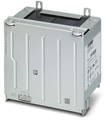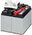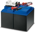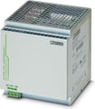
2320238
 Official Distributor
SKU
PHX2320238
MPN
QUINT-UPS/ 24DC/ 24DC/20
Weight
0.836 kg
Series QUINT-UPS
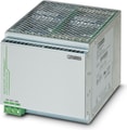
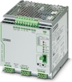
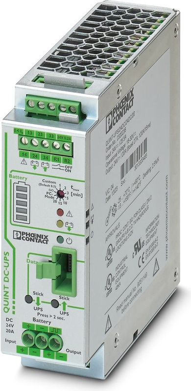
QUINT-UPS/ 24DC/ 24DC/20 - Uninterruptible power supply
Uninterruptible power supply with IQ technology for DIN rail mounting, input: 24 V DC, output: 24 V DC/20 A, including mounted universal DIN rail adapter UTA 107/30
- Easy handling thanks to automatic battery detection, tool-free battery replacement during operation, and communication via the IFS interface
- Optimum use of the buffer time and preventive monitoring of the energy storage
- Rapid battery charging
- Comprehensive signaling and parameterization
- Fast tripping of standard circuit breakers with SFB (selective fuse breaking) technology
- Reliable starting of difficult loads with the static POWER BOOST power reserve with up to 1.5 times the nominal current permanently
QUINT-UPS
The Phoenix Contact QUINT-UPS Series comprises uninterruptible power supplies (UPS) designed to ensure maximum system availability in industrial applications. These UPS modules feature IQ Technology for intelligent battery management, ensuring reliable power backup during mains failures.
Key Features:
IQ Technology: Provides real-time monitoring of the energy storage status, including parameters like voltage, current, and temperature, enabling predictive maintenance and optimal battery usage.
DIN Rail Mounting: Designed for easy integration into control cabinets with standard DIN rail mounting, facilitating straightforward installation and maintenance.
Wide Range of Models: Available in various configurations to meet different power requirements, with input and output voltages typically at 24 V DC and output currents ranging from 5 A to 20 A.
Technical Specifications
DC operation
| Input Voltage | 24 V DC |
| Nominal input voltage range | 24 V DC |
| Input voltage range | 18 V DC ... 30 V DC |
| Input voltage range DC | 18 V DC ... 30 V DC |
| Voltage type of supply voltage | DC |
| Buffer period | 1 h (With battery module 38 AH) |
| Current consumption | 32.9 A (maximum, mains operation) |
| Current consumption | 10.5 mA (No load, mains operation) |
| Current consumption | 6.9 A (Charging, mains operation) |
| Fixed backup threshold | ≤ 22 V DC |
| Variable connect threshold | 1 V/0.1 s |
Output data
| Efficiency | > 98 % (Mains operation, with charged energy storage) |
| Efficiency | 98 % (Battery operation) |
| Nominal Output Voltage | 24 V DC |
| Output voltage range | 18 V DC ... 30 V DC |
| Nominal output current (IN) | 20 A (-25 °C ... 50 °C) |
| Output current limit | In mains mode according to connected upstream current limiting device |
| Output current limit | > 27 A (Battery operation) |
| Bridging time | 7200 s |
| Derating | 60 °C ... 70 °C (2.5 %/K) |
| Derating | 60 °C ... 70 °C (2.5 %/K) |
| Output Power | 480 W |
| Power dissipation | 2.7 W (Mains operation) |
| Power dissipation | 7.65 W (Mains operation) |
| Power dissipation | 3.19 W (Battery operation) |
| Power dissipation | 9.35 W (Battery operation) |
| Connection in parallel | yes, up to 2 modules with redundancy module |
| Connection in parallel | 2 (Devices) |
| Connection in series | No |
| Connection in series | no |
Mains operation
| Nominal Output Voltage | 24 V DC |
| Output voltage range | 18 V DC ... 30 V DC |
| Nominal output current (IN) | 20 A (-25 °C ... 60 °C) |
| POWER BOOST (IBoost) | 26 A (-25 °C ... 40 °C) |
| Selective Fuse Breaking (ISFB) | 120 A (-25 °C ... 60 °C) |
| Duration | 12 ms (SFB technology) |
Battery operation
| Nominal Output Voltage | 24 V DC |
| Output voltage range | 19.2 V DC ... 27.6 V DC (UOUT = UBAT - 0,5 V DC) |
| Nominal output current (IN) | 20 A (-25 °C ... 60 °C) |
| POWER BOOST (IBoost) | 27 A (-25 °C ... 40 °C) |
| Selective Fuse Breaking (ISFB) | 120 A (-25 °C ... 60 °C) |
| Duration | 15 ms (SFB technology) |
Signal: Alarm
| Output description | Relay (floating) |
| Maximum Switching Voltage | ≤ 30 V AC/DC |
| Continuous load current | ≤ 100 mA |
Signal: Battery charge
| Output description | Relay (floating) |
| Maximum Switching Voltage | ≤ 30 V AC/DC |
| Output Voltage | 24 V |
| Continuous load current | ≤ 100 mA |
Signal: Battery mode
| Output description | Relay (floating) |
| Maximum Switching Voltage | ≤ 30 V AC/DC |
| Output Voltage | 24 V |
| Continuous load current | ≤ 100 mA |
Energy storage
| Nominal voltage UN | 24 V DC |
| End-of-charge voltage | 24 V DC ... 29 V DC (temperature compensated) |
| Charging current | 0.2 A ... 5 A |
| Nominal capacity range | 3 Ah ... 200 Ah |
| Battery presence check/time interval | 1 min. |
| Battery presence check (cyclic) | 60 s |
| IQ Technology | Yes |
| Temperature compensation | 42 mV/K (preset) |
| Temperature compensation (preset) | 42 mV/K |
| Network management | Yes |
Input
| Connection Method | Screw connection |
| Conductor cross section, rigid min. | 0.2 mm² |
| Conductor cross section, rigid max. | 6 mm² |
| Conductor cross section flexible min. | 0.2 mm² |
| Conductor cross section flexible max. | 4 mm² |
| Conductor cross section AWG min. | 12 |
| Conductor cross section AWG max. | 10 |
| Stripping length | 8 mm |
| Screw thread | M4 |
| Tightening torque, min | 0.5 Nm |
| Tightening torque max | 0.6 Nm |
Output
| Connection Method | Screw connection |
| Conductor cross section, rigid min. | 0.2 mm² |
| Conductor cross section, rigid max. | 6 mm² |
| Conductor cross section flexible min. | 0.2 mm² |
| Conductor cross section flexible max. | 4 mm² |
| Conductor cross section AWG min. | 12 |
| Conductor cross section AWG max. | 10 |
| Stripping length | 8 mm |
| Screw thread | M4 |
| Tightening torque, min | 0.5 Nm |
| Tightening torque max | 0.6 Nm |
Signal
| Conductor cross section, rigid min. | 0.2 mm² |
| Conductor cross section, rigid max. | 4 mm² |
| Conductor cross section flexible min. | 0.2 mm² |
| Conductor cross section flexible max. | 2.5 mm² |
| Conductor cross section AWG min. | 24 |
| Conductor cross section AWG max. | 12 |
| Screw thread | M4 |
| Tightening torque, min | 0.5 Nm |
| Tightening torque max | 0.6 Nm |
Interfaces
| Interface | IFS (Interface system data port) |
Signaling
| Types of signaling | LED |
| Types of signaling | Relay contact |
| Types of signaling | Interface/software |
Signal output
| Signalization designation | Power In OK |
| Status display | LED |
| Note on status display | static on |
| Note on status display | static on |
Signal output: Switching output
| Signalization designation | Alarm |
| Status display | LED |
| Note on status display | static on |
| Color | red |
| Note on status display | static on |
| Signalization designation | Battery charge |
| Status display | LED bar graph |
| Note on status display | dynamic |
| Color | green/red |
| Note on status display | dynamic |
| Signalization designation | Battery mode |
| Status display | LED |
| Note on status display | static on |
| Color | yellow |
| Note on status display | static on |
Electrical properties
| Insulation voltage input/output | 500 V DC |
| Insulation voltage input, output / housing | 750 V DC |
Product properties
| Product family | QUINT USV |
| IQ Technology | Yes |
| MTBF (IEC 61709, SN 29500) | > 500000 h (40 °C) |
Insulation characteristics
| Protection class | III |
Life expectancy (electrolytic capacitors)
| Time | 195013 h |
Dimensions
| Width | 40 mm |
| Height | 130 mm |
| Depth | 125 mm |
Installation dimensions
| Installation distance right/left | 5 mm / 5 mm |
| Installation distance top/bottom | 50 mm / 50 mm |
Alternative assembly
| Width | 123 mm |
| Height | 130 mm |
| Depth | 43 mm |
Mounting
| Mounting Type | DIN rail mounting |
| Assembly instructions | alignable: horizontal 5 mm, vertical 50 mm |
| Mounting Position | horizontal DIN rail NS 35, EN 60715 |
Material specifications
| Housing Material | Metal |
| Housing Material | Steel sheet, zinc-plated |
| Type of housing | Aluminum (AlMg3) |
| Hood version | Galvanized sheet steel, free from chrome (VI) |
Ambient conditions
| Degree of Protection | IP20 |
| Ambient Temperature (Operation) | -25 °C ... 70 °C |
| Ambient temperature (storage/transport) | -40 °C ... 85 °C |
| Climatic class | 3K3 (in acc. with EN 60721) |
| Max. permissible relative humidity (operation) | ≤ 95 % (25 °C, non-condensing) |
| Shock | 18 ms, 30g, in each space direction (according to IEC 60068-2-27) |
| Vibration (Operation) | < 15 Hz, amplitude ±2.5 mm (according to IEC 60068-2-6) |
| Vibration (Operation) | 15 Hz ... 150 Hz, 2.3g tv = 90 min. |
Standards and Regulations
| Rail applications | EN 50121-4 |
| Standard – Electronic equipment for use in electrical power installations and their assembly into electrical power installations | EN 50178/VDE 0160 (PELV) |
| Standard - Electrical safety | EN 60950-1/VDE 0805 (SELV) |
Approvals
| UL approvals | UL Listed UL 508 |
| UL approvals | UL/C-UL Recognized UL 60950-1 |
| UL approvals | UL ANSI/ISA-12.12.01 Class I, Division 2, Groups A, B, C, D (Hazardous Location) |
EMC data
| Low Voltage Directive | Conformance with Low Voltage Directive 2014/35/EC |
| EMC requirements for noise emission | EN 61000-6-3 |
| EMC requirements for noise emission | EN 61000-6-4 |
| EMC requirements for noise immunity | EN 61000-6-1 |
| EMC requirements for noise immunity | EN 61000-6-2 |
| Electromagnetic compatibility | Conformance with EMC Directive 2014/30/EU |
Electrostatic discharge
| Standards/regulations | EN 61000-4-2 |
| Contact discharge | 8 kV (Test Level 4) |
| Discharge in air | 15 kV (Test Level 4) |
| Comments | Criterion A |
Electromagnetic HF field
| Standards/regulations | EN 61000-4-3 |
| Frequency Range | 80 MHz ... 1 GHz |
| Test field strength | 20 V/m |
| Frequency Range | 1 GHz ... 3 GHz |
| Test field strength | 10 V/m |
| Frequency Range | 2 GHz ... 3 GHz |
| Test field strength | 3 V/m |
| Comments | Criterion A |
Fast transients (burst)
| Standards/regulations | EN 61000-4-4 |
| Input | 2 kV (Test Level 3 - asymmetrical) |
| Output | 2 kV (Test Level 3 - asymmetrical) |
| Signal | 2 kV (Test Level 4 - asymmetrical) |
| Comments | Criterion A |
Surge voltage load (surge)
| Standards/regulations | EN 61000-4-5 |
| Input | 0.5 kV (Test Level 1 - symmetrical) |
| Input | 0.5 kV (Test Level 1 - asymmetrical) |
| Output | 0.5 kV (Test Level 1 - symmetrical) |
| Output | 0.5 kV (Test Level 1 - asymmetrical) |
| Signal | 1 kV (Test Level 2 - asymmetrical) |
| Comments | Criterion B |
Conducted interference
| Standards/regulations | EN 61000-4-6 |
| I/O/S | asymmetrical |
| Frequency Range | 0.15 MHz ... 80 MHz |
| Comments | Criterion A |
| Voltage | 10 V (Test Level 3) |
Emitted interference
| Standards/regulations | EN 61000-6-3 |
| Radio interference voltage in acc. with EN 55011 | EN 55011 (EN 55022) Class B, area of application: Industry and residential |
| Emitted radio interference in acc. with EN 55011 | EN 55011 (EN 55022) Class B, area of application: Industry and residential |
Criteria
| Criterion A | Normal operating behavior within the specified limits. |
| Criterion B | Temporary impairment to operational behavior that is corrected by the device itself. |
Accessories
Why Proax for Phoenix Contact 2320238?
Proax is an authorized distributor of Phoenix Contact 2320238 and one of Phoenix Contact's largest distributors in North America. Our highly skilled in-house technical team is ready to assist with any technical needs.
Have a question in mind? to help you get the right product as quickly as possible for your project. We're always here to help!
Short Lead Time
Highly Trained Staff
Live Chat
Technical Support
Local Inventory
60+ Years Experience
Additional Information
| Pack Size | 1 |
Recommended
 The redundancy set consists of two QUINT-PS/1AC/24DC/10 power supplies combined with the active QUINT-ORING/24DC/2X10/1X20 redundancy module, so as to guarantee maximum availability of your system.Primary-switched QUINT POWER supply for DIN rail mounting with SFB (selective fuse breaking) technology, input: 1-phase, output: 24 V DC/10 AActive QUINT redundancy module for DIN rail mounting with Auto Current Balancing ACB technology and monitoring functions, input: 24 V DC, output: 24 V DC/2 x 10 A or 1 x 20 A, including mounted UTA 107/30 universal DIN rail adapter


