
































Search blog posts
Search blog posts
170 articles
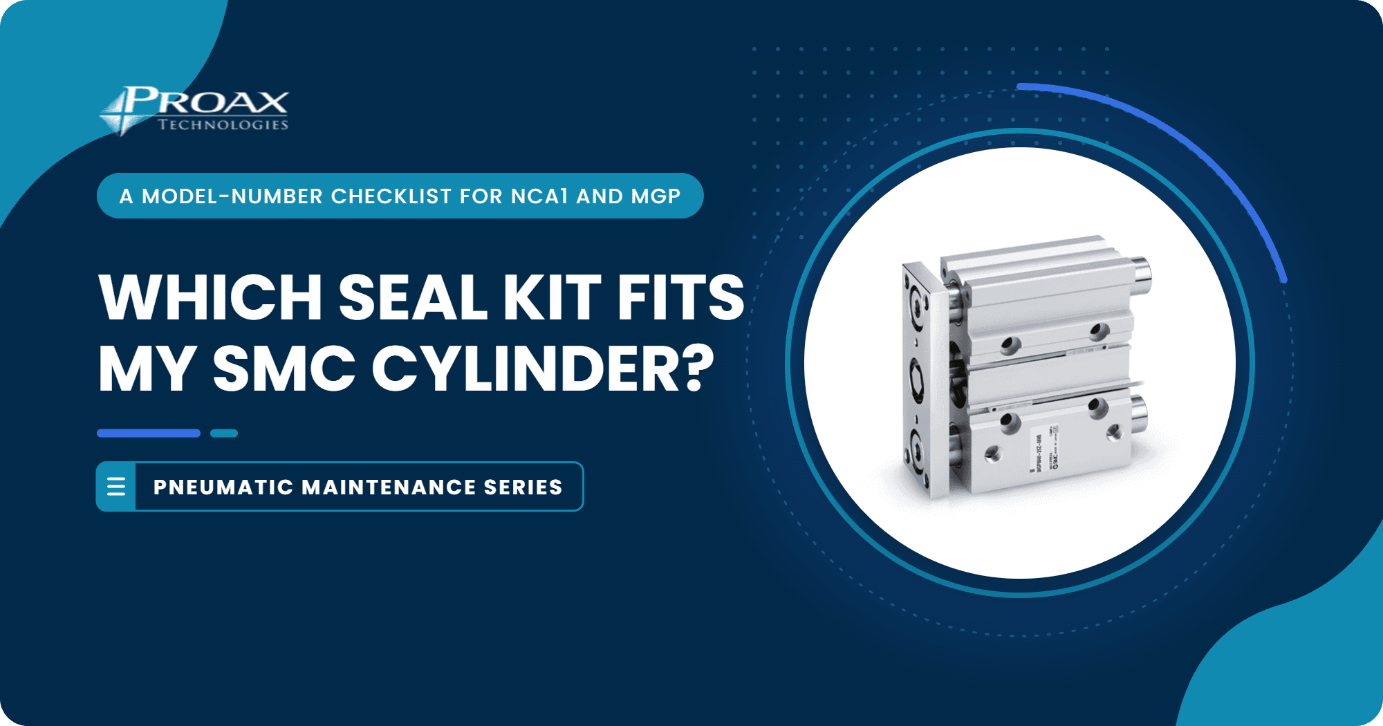
PneumaticsWhich Seal Kit Fits My SMC Cylinder? A Model-Number Checklist for NCA1/NC1A and MGP
Nov 5, 2026|
Quick Answer
Start with the full model number on the label, including every suffix. Confirm the series and bore, find SMC’s parts list for that exact series, then check whether the cylinder is serviceable and which seals the kit contains. If the label is incomplete or a suffix is unfamiliar, send photos to technical support before ordering.
Model Number→Series and Bore→OEM Parts List→Serviceability→Order the Kit
Three recent live chats asked the same question in three different ways. Each answer starts in the same place: the model number on the label.
Three Questions From Recent Live ChatsNCA1B400-1200
Which Seal Kit Fits This Tie-Rod Cylinder?
NC1A250-0300-XA39MB5
What Is the Kit Reference for This Number?
MGPL25-125Z
Do Repair Kits Exist for This Compact Guide Cylinder?
1. Record the Full Model Number and Every Suffix
Copy the model number from the cylinder’s label exactly, including the dashes and everything after the stroke, and take a photo of the label. Purchase records and memory are useful backups, but cylinders get swapped, modified and relabelled over the years.
Example LabelNCA1B400-1200-XC22NCA1SeriesTie-RodBMountingBasic400Bore4 in1200Stroke12.00 inXC22SuffixViton Seals
The suffix is the easiest part to miss, and it can change which seals fit.
Rule of Thumb
If you can’t read the whole model number, you can’t pick the kit. A clear label photo is the fastest fix.
2. Confirm the Series
The first letters identify the product family. Seal kits are designed for one series, so never assume a kit from one family fits another, even at a similar bore.
SMC NCA1
Tie-Rod Cylinder
* NFPA-Style Tie-Rod Construction
* Bore and Stroke Codes in Inches
* Seal Kits Listed in the Series Catalog
* Standard Kits Exclude Several Options
SMC MGP
Compact Guide Cylinder
* Slide Bearing (M) or Ball Bushing (L, A) Versions
* Bore and Stroke in Millimetres
* Seal Kit Search on SMC’s Maintenance Site
* One MGP-Z Kit per Bore
Kits Do Not Cross Series
Watch Out for Part Numbers
SMC uses the NC1A prefix on NCA1 component parts, such as seal kits and cylinder tubes. A number like NC1A250-0300-XA39MB5 does not follow the standard NCA1 ordering format and carries a special suffix, so it needs a factory lookup rather than a catalog search.
3. Confirm the Bore and Units
Seal kits are ordered by bore, so read it carefully and note the units. In NCA1 model numbers, the bore code is in inches and the stroke is in inches and hundredths: NCA1B400-1200 has a 4 in bore and a 12.00 in stroke. MGP model numbers use millimetres: MGPL25-125Z is a 25 mm bore, 125 mm stroke cylinder with ball bushing bearings.
4. Find the OEM Parts List for That Series
SMC publishes replacement parts information by series. Its maintenance site includes a seal kit search for many cylinder families, including the MGP. For series that are not listed there, such as the NCA1, SMC points to the replacement parts list in the series catalog.
SMC Maintenance Parts List
Seal kit search by series, including the MGP.
Open the Site →
MGP-Z Parts List
One seal kit per bore for MGPM, MGPL and MGPA.
View the PDF →
NCA1 Series Catalog
Replacement parts listed with the construction drawing.
View the PDF →
5. Check Whether Options Change the Kit
Standard kits are written for standard cylinders. SMC’s NCA1 catalog says its seal kits are for standard single rod, double acting cylinders without options, and that they do not apply to the following:
WDouble Rod CylindersTTrunnion MountsXC8 / XC9Adjustable Stroke OptionsXB5Oversized Rod With Front Mount
Kits for these options are confirmed through SMC.
6. Decide Whether the Cylinder Is Worth Resealing
Before ordering, check where the air is leaking and inspect the rod and bore surfaces. If they are damaged, compare the cost and downtime of a repair with a new cylinder.
A Seal Kit Replaces
* Piston and Rod Seals
* Gaskets
* Cushion Seals, Where Fitted
A Seal Kit Won’t Fix
* A Scored or Bent Piston Rod
* A Worn or Damaged Cylinder Tube
* Worn Guide Bearings
7. Send the Right Details When the Label Is Incomplete
If the label is worn, painted over or missing, or the model number does not match the series format, contact technical support before ordering anything. A few clear photos usually settle the question faster than a description.
Label Close-Up
Every Character Readable
Whole Cylinder
Shows Series and Size
Mounting
Brackets and Bolt Pattern
Rod End
Thread and Attachments
Add the measured bore and stroke if the label is missing.
What the Three Requests Tell Us
Model NumberSeriesBore and StrokeNext StepNCA1B400-1200NCA1 Tie-Rod, Basic Mount4 in Bore, 12.00 in StrokeUse the NCA1 Parts ListNC1A250-0300-XA39MB5Not ConfirmedNot ConfirmedSend Label PhotosMGPL25-125ZMGP-Z Compact Guide, Ball Bushing25 mm Bore, 125 mm StrokeUse the MGP-Z Parts List
Decoded from SMC’s NCA1 series catalog and MGP-Z documentation. Kit numbers and serviceability are confirmed by technical support before ordering.
Seal Kit Basics
01
Model Number First
The full label number, including every suffix, decides the kit.
02
Series
NCA1 and MGP use different kits and parts lists.
03
Bore
Kits are ordered by bore. Check whether it is in inches or millimetres.
04
Options
Suffixes such as double rod or Viton seals can need a different kit.
05
Grease
The MGP-Z kit does not include grease. Order the grease pack separately.
06
Serviceability
A kit replaces seals and gaskets, not a worn rod, tube or bearing.
Sources: SMC MGP-Z maintenance parts list and SMC NCA1 series catalog.
Checklist: What to Send Proax Before Ordering a Seal Kit
A Seal Kit Request Goes Faster With This Information:
Full Model Number, Including Every SuffixPhotos of the Label and the Whole CylinderSeries and Bore, With UnitsStroke and Mounting StyleRod Type, Such as Single or Double RodAny Special Seals or OptionsWhere the Cylinder Is LeakingCondition of the Rod and TubeQuantity and Date Needed
Proax Technical Support
Not Sure Which Kit Fits?
Send your model number and label photos, and our in-house team will help you find the right kit or the right next step.
Contact UsLearn More About SMC at Proax
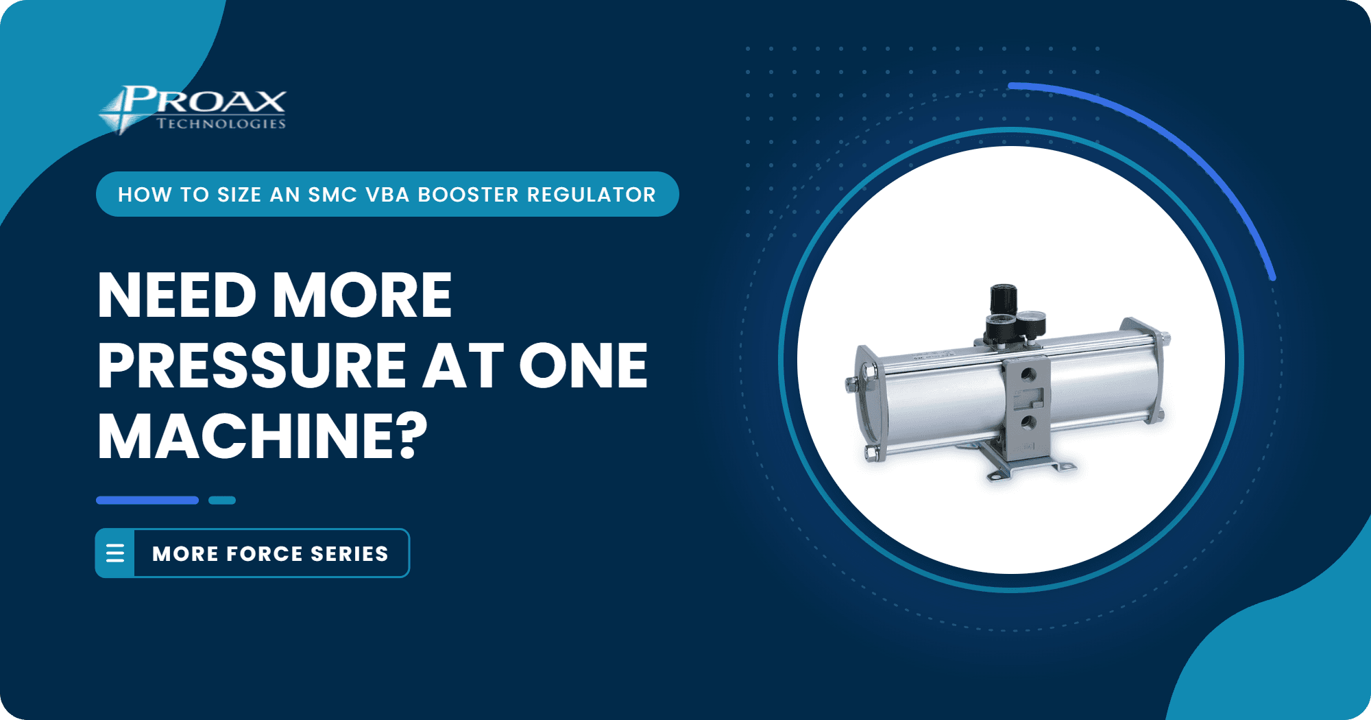
PneumaticsNeed More Pressure at One Machine? How to Size an SMC VBA Booster Regulator
Oct 29, 2026|
Quick Answer
A booster regulator such as the SMC VBA raises air pressure locally, up to twice the supply pressure on standard models, so one machine can get more force without raising pressure across the whole plant. Before choosing one, work out the pressure you need at the actuator, check the flow and whether demand is continuous or intermittent, and confirm that everything downstream is rated for the boosted pressure. Then pick the model, decide on an air tank and plan the installation.
Pressure Needed→Flow and Duty→Downstream Ratings→Model and Tank→Installation
This post follows on from our guide to the SMC CQE high-power compact cylinder, which covered three ways to get more force from a compact cylinder: more piston area, a bigger bore or more pressure. Here we look at the pressure route in more detail, using an SMC VBA booster regulator to raise pressure at a single machine.
When a Booster Comes UpLine Pressure
The Plant Line Sags Below What One Station Needs
One Machine
A Single Press or Clamp Needs More Force Than the Rest
No Space
There Is No Room for a Bigger Cylinder
1. How Much Pressure Do You Need at the Actuator?
Start with force, then work back to pressure. Divide the force you need by the piston area on the side that does the work. On retraction, the rod takes up part of that area, so the same pressure gives less force.
Pressure NeededMeasured at the Actuator, Not the CompressorForceLoad, Friction, Acceleration÷Piston AreaBore, Minus Rod on Retract=PressureAt the Actuator
For a 32 mm bore, the piston area on extension is about 804 mm², so every 0.1 MPa adds roughly 80 N of theoretical force.
Bore0.4 MPa (58 psi)0.5 MPa (73 psi)0.65 MPa (94 psi)0.8 MPa (116 psi)32 mm
Extension322 N402 N523 N643 N40 mm
Extension503 N628 N817 N1005 N
Theoretical force, F = P × A, before friction and acceleration. Psi values are rounded.
Measure at the Machine
Check the pressure at the actuator while the machine cycles. If it only sags during peak demand, fixing the supply line or adding a tank may solve it without a booster.
2. Is a Booster the Right Route?
A booster makes the most sense when one machine needs more pressure than the rest of the plant. Raising the compressor setting pushes every line higher, while a booster keeps the main line where it is and raises pressure only where it is needed.
Booster or Higher Plant Pressure?Local
Add a Booster
* Raises Pressure at One Machine
* Main Line Stays Where It Is
* Needs Space, Piping and an Exhaust
* Uses Part of the Supply Air to Drive Itself
Plant-Wide
Raise Plant Pressure
* Every Line Runs Higher
* No Extra Hardware at the Machine
* Every Component Must Be Rated for It
* Compressor Works Harder Across the Plant
3. How Much Air Does It Need, and How Often?
A booster drives itself with part of the incoming air, so the supply has to provide more air than comes out of the outlet. Check the flow the machine needs and whether that demand is continuous or comes in short bursts, then compare it with the booster's flow at your pressures using SMC's selection charts.
Intermittent
Add an Air Tank
A VBAT tank on the outlet stores boosted air for short peaks, such as a clamp or press stroke, so a smaller booster can keep up.
Continuous
Size the Booster for It
A tank does not help with continuous demand. SMC advises confirming life for continuous operation and choosing a larger booster if needed.
4. Is Everything Downstream Rated for the Boosted Pressure?
Every part after the booster sees the higher pressure: hoses, fittings, valves, regulators and the actuator itself. Check each rating before you set the outlet pressure.
1.0 MPa
CQ2 Maximum Pressure
A 32 mm CQ2 boosted from 0.5 to 0.65 MPa gives about 523 N on extension, inside its rating.
0.7 MPa
CQE Maximum Pressure
A booster does not help a CQE that already needs more than 0.7 MPa. Its extra force comes from piston area instead.
Rule of Thumb
Set the booster outlet below the lowest maximum operating pressure of anything it feeds, and leave a margin.
5. Which VBA Model Fits?
The standard VBA models double the supply pressure, with handle or air-operated adjustment. Port size and flow rise with body size, and the VBA11A covers higher ratios at low flow.
ModelIncreaseSet PressureMax Flow (ANR)Port (Rc)AdjustmentVBA10A-022×0.2–2.0 MPa230 L/min1/4HandleVBA11A-022 to 4×0.2–2.0 MPa70 L/min1/4HandleVBA20A-032×0.2–1.0 MPa1000 L/min3/8HandleVBA22A-032×0.2–1.0 MPa1000 L/min3/8Air-operatedVBA40A-042×0.2–1.0 MPa1900 L/min1/2HandleVBA42A-042×0.2–1.0 MPa1900 L/min1/2Air-operatedVBA43A-042×0.2–1.6 MPa1600 L/min1/2Handle
From SMC VBA product data. Supply pressure range is 0.1 to 1.0 MPa on every model listed. G, NPTF and made-to-order NPT threads are also available, along with gauge and silencer options. Check SMC flow charts at your own inlet and outlet pressures.
Air-Operated Adjustment
The VBA22A and VBA42A set the outlet with a pilot pressure, which suits remote adjustment. The handle models are set at the unit.
6. What Does the Installation Need?
Inlet Mist Separator
SMC recommends an AM mist separator on the inlet, close to the booster. The inlet mesh cannot remove dust continuously or separate drainage.
Horizontal Mounting
Mount the booster horizontally, with the tie-rods and cover level, or it may malfunction.
Dedicated Exhaust
Give each booster its own exhaust line, since joined exhausts can create back pressure. Silencer options reduce exhaust noise.
Air Tank on the Outlet
Add a VBAT tank for intermittent peaks. Sizes run from 5 to 38 L, in carbon or stainless steel.
Air Quality
Very dry air, with a dew point of −23 °C or lower, can shorten life by drying out the internal grease.
Maintenance Kits
SMC lists maintenance kits by model. Constant bleed from under the handle, or exhaust noise with no outlet demand, are signs of wear.
7. Is the Model Available When You Need It?
Lead times can differ between models and thread options. Ask Proax to check current availability for each candidate part number, along with the mist separator and tank.
Where the SMC VBA Fits
The VBA suits a single press, clamp or test station that needs more pressure than the plant line provides, especially where demand comes in bursts that an air tank can cover.
01
Local Boost
Raises pressure at one machine, up to twice the supply on standard models.
02
Air Driven
Runs on compressed air alone, with no electrical supply.
03
Adjustable
Outlet pressure is set by handle, or by pilot pressure on air-operated models.
04
Sizes
1/4, 3/8 and 1/2 Rc ports, from 230 to 1900 L/min maximum flow.
05
Air Tanks
VBAT tanks from 5 to 38 L store boosted air for short peaks.
06
Higher Ratio
The VBA11A boosts 2 to 4 times for low-flow applications.
Sources: SMC VBA booster regulator series and the SMC booster regulator VBA series catalog.
When Another Route May Be Better
* The Whole Plant Needs More Pressure
* Demand Is High and Continuous
* The Actuator Is Already at Its Maximum Pressure
* A Larger Bore or a High-Power Cylinder Such as the SMC CQE Fits
* The Pressure Only Sags Because of an Undersized Supply Line
Checklist: What to Gather Before You Contact Proax
A Booster Sizing Review Goes Faster With This Information:
Force Needed, and the Actuator Bore and StrokeSupply Pressure Measured at the MachinePressure Needed at the ActuatorAir Flow and Cycle Rate, Continuous or IntermittentMaximum Pressure of Every Downstream ComponentPort Size and Thread TypeSpace Available, and Where the Exhaust Can GoExisting Filters or Mist Separators on the Line
Proax Technical Support
Need More Pressure at One Machine?
Send us the force, supply pressure and air flow you're working with, and our in-house team will help you size a booster and check lead times.
Contact UsLearn More About SMC at Proax
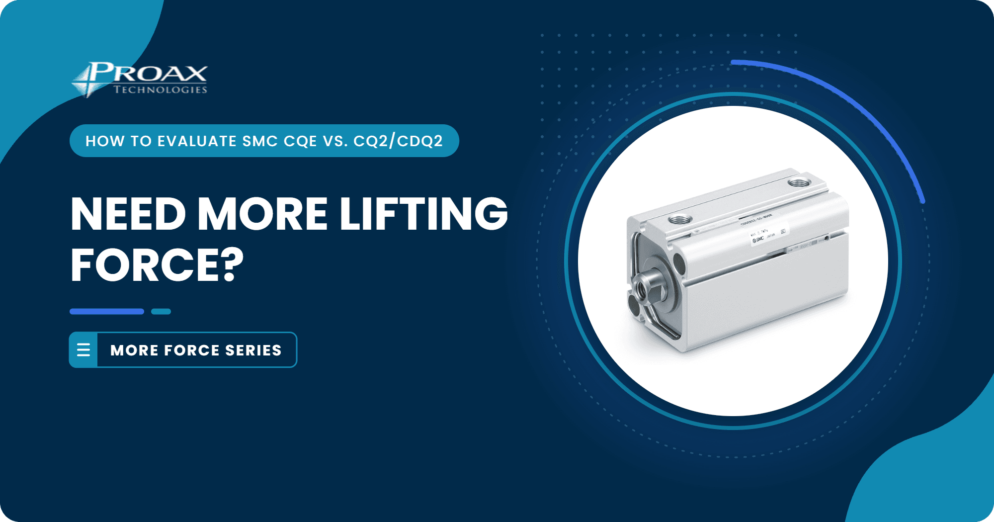
PneumaticsNeed More Lifting Force from a Compact Cylinder? How to Evaluate SMC CQE vs. CQ2/CDQ2
Oct 22, 2026|
Quick Answer
To get more lifting force from a compact cylinder, calculate the force at your actual operating pressure, in the direction that does the lifting, then choose a route: a high-power SMC CQE in the same body size, the next bore up in the standard CQ2 line, or more pressure on the existing cylinder. None of these is automatically a drop-in replacement, so confirm bore, stroke, mounting, rod end, ports and sensors, then check current availability with Proax.
Force Needed→Choose a Route→Force at Real Pressure→Fit Checks→Availability
A familiar request: a 32 mm compact cylinder on a lift or press station does its job, but the process now needs roughly 25 to 30% more force, and the high-power replacement is made to order. The steps below show how to compare an SMC CQE high-power compact cylinder with a CQ2/CDQ2, and when a different route is the better answer.
Three Requests Behind This PostCDQEB32-25
Is There a Faster-Available Option With 25 to 30% More Lifting Force?
CQ2
What Is the Current Lead Time on a Standard Compact Cylinder?
32 mm × 90–100 mm
Which Cylinder Has This Bore and Stroke?
1. How Much Force Does the Lift Really Need?
Start with the load, not the cylinder. Then compare that need with what the current cylinder delivers. "25 to 30% more" only becomes useful once it is a number of newtons at a known pressure.
Force NeededThen Note Which Stroke Does the Liftingm × 9.81Load Weight+Guides + SealsFriction+m × aAcceleration=TotalForce Needed
Pushing up from below lifts on extension. Pulling up from above lifts on retraction, which has less piston area because of the rod.
Rule of Thumb
Theoretical output is not usable force. Many designers keep a moving load to about half of theoretical output to leave margin for friction, acceleration and pressure drop.
2. Which Route Gets You There?
There are three common ways to get more force from a compact cylinder application. All three can reach a 25 to 30% target; the right one depends on the space around the cylinder, the mounting, the pressure available and the lead time on each part.
What to Check for Each RouteSame Body
High-Power Piston
* Same 45 mm Square Body
* 0.7 MPa Maximum Pressure
* One Standard Mounting Style
* Check the Made-to-Order Lead Time
Bigger Body
Next Bore Up
* Body Grows From 45 to 52 mm Square
* Mounting Holes Move
* Needs More Space Around the Cylinder
* Standard Line, Often Easier to Source
Same Cylinder
More Pressure
* No Hardware Change
* CQ2 Rated to 1.0 MPa
* Check the Valve, Fittings and Load
* Confirm With Your Risk Assessment
3. What Force Does Each Option Give at Your Actual Pressure?
Theoretical force is pressure times piston area: F = P × A. For a round piston, A = π × D² ÷ 4 on extension, minus the rod area on retraction. The CQE’s polygonal piston gives a size 32 body about the piston area of a 40 mm bore, so use SMC’s output table for the CQE instead of the round-bore formula.
OptionBody0.4 MPa (58 psi)0.5 MPa (73 psi)0.6 MPa (87 psi)32 mm CQ2
Starting Point45 mm322 N402 N483 NSMC CQE Size 32
High-Power Piston45 mm482 N603 N724 N40 mm CQ2
Next Bore Up52 mm503 N628 N754 N
Theoretical extend force. CQE values from the SMC CQE series catalog; 32 mm CQ2 from SMC data at 0.5 MPa, scaled by pressure; 40 mm CQ2 calculated from bore area. Retract force is lower because of the rod.
Measure at the Cylinder
Measure pressure at the cylinder while the machine cycles, not at the compressor. Long lines, small valves and shared headers can leave the cylinder well below the regulator setting.
Worked Example
At 0.5 MPa, a 32 mm CQ2 extends with 402 N, so a 25 to 30% increase means about 503 to 523 N. A CQE size 32 gives 603 N at the same pressure, about 50% more. If the line at the cylinder sags to 0.4 MPa, the CQE gives about 482 N and misses the target.
1.0 MPa
CQ2 Maximum Pressure
Raising a 32 mm CQ2 to about 0.65 MPa gives roughly 523 N on extension, if the circuit allows it.
0.7 MPa
CQE Maximum Pressure
The CQE gets its extra force from piston area, not pressure. Do not plan above 0.7 MPa.
4. Do the Bore and Stroke Match?
Bore and Stroke Alone Don’t Identify a Cylinder
A request for about 32 mm bore and 90 to 100 mm stroke can turn out to be a round-body cylinder rather than a compact one. Read the full part number from the label, or send photos of the label, body, mounting, rod end and ports.
If you are moving to a CQE, check that its size and stroke range cover what you need:
20 / 25 / 32 / 40CQE Body Sizes5–50 mmStandard Strokes, All Sizes75 / 100 mmExtra Strokes on Sizes 32 and 40-XB10Made-to-Order Exclusive Body for Intermediate Strokes
Intermediate strokes come in 1 mm steps, either as a spacer in a longer body or as an exclusive body, and the two have different overall lengths.
5. Will the Mounting and Body Fit?
In a part number such as NCDQ2A32-25DZ, the A means both ends tapped. Compare the drawing with the installed part either way, and check body length at the chosen stroke, bolt pattern and bolt length.
CQ2 Family
Several Mounting Styles
* Both Ends Tapped (A)
* Through-Hole
* Foot, Flange and Clevis Options
* 45 mm Square Body on the 32 mm Bore
SMC CQE
One Standard Body
* Through-Hole and Both Ends Tapped
* Same External Dimensions as the CQ2
* Mounting Bolts Ordered Separately
* Foot, Flange or Clevis Setups Need a Closer Look
6. Do the Rod End, Ports, Sensors and Load Limits Work?
Rod End
Female thread is standard, with a male-thread option and made-to-order rod end shapes. Match the existing floating joint or tooling.
Rod Rotation
The polygonal piston keeps the rod from turning in normal operation, but it is not a guide for side loads.
Ports
The CQE catalog lists Rc1/8 ports on sizes 32 and 40. Confirm the thread on the existing fittings.
Auto Switches
With the built-in magnet, the CQE takes SMC’s compact D-M9 solid-state switches. Check the model and wiring.
Load Limits
Check piston speed, allowable kinetic energy and lateral load at the rod end. More force does not raise these limits.
Lead Time
Made-to-order and standard parts can have very different delivery times. Check each candidate.
7. Is the Part Available When You Need It?
Lead time can decide between technically sound options. A made-to-order CQE and a standard CQ2 or NCQ2 configuration can have very different delivery times, and both change. Send Proax the exact candidate part numbers so we can check current availability and lead time for each before you commit.
Where the SMC CQE Fits
The SMC CQE may suit lifts, clamps and press-fits that need more force in the same space, or the same force at a lower pressure. Explore SMC at Proax for configuration and quotes.
01
More Force
Size 32: 603 N on extension at 0.5 MPa, compared with 402 N for a 32 mm CQ2.
02
Lower Pressure
Size 32 reaches about 402 N at 0.33 MPa, where a 32 mm CQ2 needs 0.5 MPa.
03
Sizes and Strokes
Sizes 20, 25, 32 and 40. Strokes 5 to 50 mm, plus 75 and 100 mm on sizes 32 and 40.
04
Mounting
One standard body: through-hole and both ends tapped.
05
Rod
Non-rotating in normal operation thanks to the polygonal piston. Female or male rod end.
06
Sensing
Built-in magnet option with compact D-M9 solid-state auto switches.
Sources: SMC CQE series product information and SMC CQE series catalog.
When a CQ2 or CDQ2 May Still Be the Better Choice
* The Circuit Runs Above 0.7 MPa
* The Machine Uses a Foot, Flange or Clevis Mount
* The Stroke Is Longer Than 100 mm
* There Is Room for a 52 mm Body and a 40 mm Cylinder Meets the Target
* A Modest Pressure Increase on the Existing CQ2 Covers the Target
Checklist: What to Gather Before You Contact Proax
A Compact Cylinder Replacement Review Goes Faster With This Information:
Full Part Number, or Photos of the Label and BodyBore or Body Size, Rod Diameter and StrokeLoad Weight, and Whether It Lifts on Extend or RetractAir Pressure Measured at the CylinderMounting Style, Bolt Pattern and Space Around the BodyRod End Thread and Attached HardwarePort Thread and FittingsAuto Switch Model, Wiring and QuantityDate the Replacement Is Needed
Proax Technical Support
Need More Force From the Same Space?
Send your current part number, operating pressure and load, and our in-house team will help you compare options and check lead times.
Contact UsLearn More About SMC at Proax

RoboticsHow to Choose a Robotic Tool Changer: 7 Questions Engineers Should Ask
Oct 16, 2026|
Quick Answer
To choose a robotic tool changer, size it for the moment load of your heaviest tool, not for payload alone. Then confirm that it passes the air, power and signals each tool needs, stays locked if air pressure is lost, repeats accurately enough for the process, and fits your robot flange, storage layout and environment.
Tools→Moment Load→Pass-Through→Loss of Air→Repeatability→Storage→Flange
1. What Tools Will the Robot Change, and How Often?
List every end effector the robot will carry: grippers, vacuum tooling, screwdrivers, dispensing heads. Include tools planned for later, because the changer is sized for the worst case.
Then estimate changes per shift and compare your yearly count with the rated life.
Cycle CountCompare the Result With the Rated LifeChangesPer Shift×ShiftsPer Day×DaysPer Year=TotalYearly Changes
A changer swapping every cycle builds up cycles far faster than one used only for changeovers.
2. What Payload and Moment Load Must It Carry?
Robot tool changer payload is only the starting point. The number that decides the size is moment load: tool weight multiplied by the distance from its centre of gravity to the coupling face.
Calculate the moment for your heaviest or longest tool, then check the conditions behind any payload rating, since ratings assume a stated acceleration and centre-of-gravity offset. To see payload by flange size, review Zimmer WPR5000 sizes and features.
Rule of Thumb
Allow two to three times the static moment to cover robot motion.
3. What Air, Power, Signals or Fluids Must Pass Through?
Every Utility Has to Cross the Coupling
Air and Vacuum
Compressed air and vacuum, with the flow each tool requires.
Sensor and I/O Signals
Tool-present, gripper position and other inputs and outputs.
Power
For electric grippers or servo tools.
Fieldbus or Ethernet
Communication for smart tools and I/O modules.
Hydraulics or Coolant
Fluid lines for tools that need them.
Spare Capacity
Check which are built in and which need add-on modules, and leave room to grow.
4. What Happens if Air Pressure or Power Is Lost?
Many units are pneumatic tool changers, so ask what holds the tool when air fails or an emergency stop vents the system. Look for a mechanical lock that holds without pressure.
Then ask how the controller knows the coupling state.
Coupling States the Controller Should See
Locked
The coupling is closed and holding the tool.
Unlocked
The coupling is open and ready to release or pick up.
Tool Present
A tool is seated on the coupling.
With all three signals, the program can refuse to move on a bad connection.
If your risk assessment calls for a performance level, confirm which options it depends on.
5. What Repeatability Does the Process Need?
Each change must return the tool to the same position. Compare the stated repeatability with your process tolerance, and ask about rigidity, because a coupling that flexes under load shifts the tool point.
6. How Will Idle Tools Be Stored and Picked Up?
Tools not in use sit in a storage station, also called a tool stand. Check the approach path, the misalignment the station tolerates at pick-up and whether sensors confirm a tool is present.
7. Does It Fit the Robot Flange and the Environment?
Many industrial robot flanges follow ISO 9409-1, which defines the bolt pattern by pitch circle diameter. A changer with the same pitch circle mounts directly; a mismatch needs an adapter plate, which adds height and weight. Then match the IP rating and temperature range to the cell.
ISO 9409-1Common Robot Flange StandardPCDMatch the Pitch Circle DiameterAdapterAdds Height and Weight If Patterns DifferIPMatch the Rating and Temperature to the Cell
Where the Zimmer WPR5000 Fits
The Zimmer WPR5000 is a pneumatic robot end-effector changer. It may suit cells that need the tool held if air is lost, repeatable positioning and an ISO-pattern flange. Explore the Zimmer WPR5000 tool changer, then click Get Custom Quote to request datasheets and pricing.
01
Moment Load
Flat design reduces flange torque. Maximum moments from 100 N·m (TK 40) to 2,500 N·m (TK 160).
02
Pass-Through
Four to ten built-in air feed-throughs, plus optional energy elements for signals, power and hydraulics.
03
Loss of Air
A spring-loaded, self-locking piston keeps the tool attached when air is lost.
04
Safety Level
Meets Performance Level d, category 3 requirements with optional sensors.
05
Repeatability
0.01 mm in Z, 0.02 mm in X and Y.
06
Flange and Environment
EN ISO 9409-1 mounting, TK 40 to TK 160. IP54, corrosion protected.
Source: Zimmer Group WPR5000 datasheets.
Checklist: What to Gather Before You Contact a Supplier
Robotic Tool Changer Selection Goes Faster With This Information:
Robot Model and Flange Pitch CircleWeight and Centre-of-Gravity Distance of Each ToolRobot Acceleration or Target Cycle TimeAir, Electrical, Data and Fluid Lines per ToolNumber of Tools, Changes per Shift and Storage SpaceRequired Repeatability at the Tool PointSafety Requirements From the Risk AssessmentEnvironment: Dust, Coolant, Washdown, Temperature
Proax Application Support
Ready to Size Your Tool Changer?
Bring your checklist to Proax for application support from our in-house engineers.
Contact UsLearn More About Zimmer Tool Changers
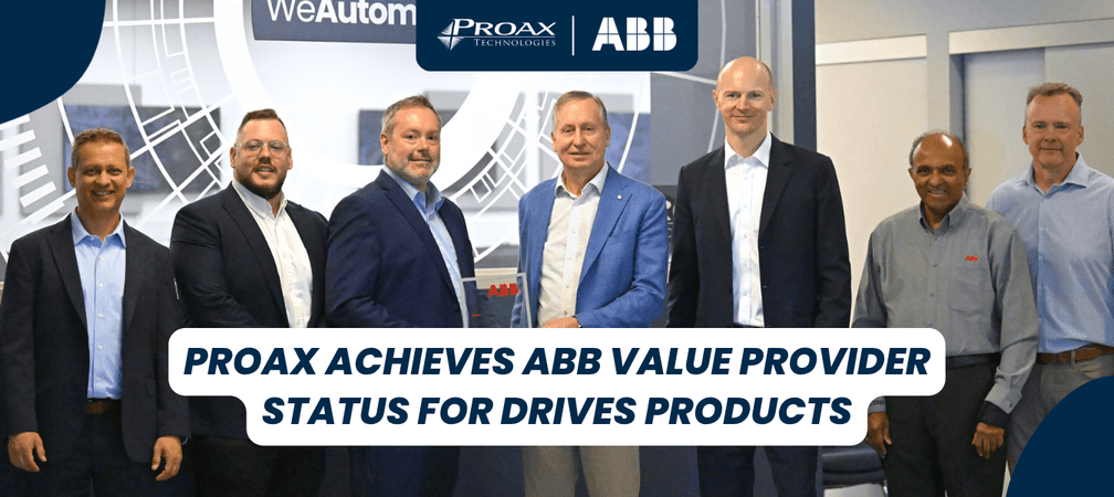
NewsProax Achieves ABB Value Provider Status for Drives Products
Sep 17, 2026|
Proax is proud to announce its official recognition as an ABB Value Provider (AVP) marking a significant milestone in the company's commitment to delivering comprehensive drives expertise to Canadian customers.
The AVP authorization recognizes Proax's demonstrated commitment to consistent quality, deep understanding of local markets, and technical support. As an official ABB AVP, Proax brings ABB's complete drives portfolio, including AC and DC drive systems, and motion control systems, directly to industry professionals across Canada with the reliability and local presence they depend on.
What AVP Authorization Means
Proax's AVP status means the company is highly trained, regularly audited, and officially authorized to deliver technical support. This designation strengthens Proax's ability to serve the Canadian market with complete product knowledge, and the local support that drives efficient, productive operations.
Strategic Win for Canada's Industrial Ecosystem
This authorization is a key part of ABB Canada's local-for-local strategy, designed to strengthen service and presence across Canadian markets. By partnering with trusted national providers like Proax backed by ABB's global standard, Canadian operations benefit from proven energy-efficient solutions that help lower operating costs and reduce energy consumption, dependable reliability and uptime with local support when it matters most.
"Being authorized as an ABB Value Provider is recognition of Proax's commitment to delivering world-class products and expertise to Canadian customers. This status strengthens our ability to serve our customers with complete product knowledge and the reliability that drives efficient, productive operations across Canada." – Stephen Daub, President, Proax Technologies
“Proax joining as an AVP is exactly the kind of partnership we're looking for. They're committed, they know the market, and they are dedicated to enabling all industries to drive sustainable business growth” - Ryan Clancy, National Sales Director for Distribution, ABB, Motion Drive Products.
Recently, Proax hosted Tuomo Hoysniemi, ABB’s Division President for Motion Drive Products, and the dedicated national account team on-site to celebrate this milestone, a testament to the strength of partnership built on people and shared commitment to customer success.
Proax Technologies, is a leading Technical Automation Distributor that offers innovative product solutions in the areas of Automation and Robotics, Motion Control and Machine Safety; creating close relationships with our valued customers, vendors and employees. We've been in the marketplace for over 59 years and we continue to grow and expand our product line and services to meet our customer's needs.
ABB Motion, a global leader in motors and drives, is at the core of accelerating a more productive and sustainable future. We innovate and push the boundaries of technology to contribute to energy efficient, decarbonizing and circular solutions for customers, industries and societies. With our digitally enabled drives, motors and services we support our customers and partners to achieve better performance, safety and reliability. To help the world’s industries outrun – leaner and cleaner, we deliver motor-driven solutions for a wide range of applications in all industrial segments. Building on over 140 years of domain expertise in electric powertrains, our more than 23,000 employees across 100 countries learn and improve every day. go.abb/motion
AutomationIPD Connectors: The Future of Tool-Free Power Distribution
Sep 17, 2025|
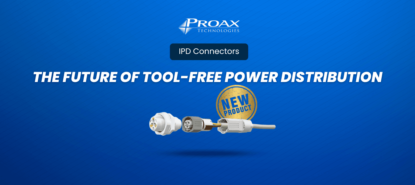
When it comes to reliable, efficient power distribution in challenging industrial environments, IPD (Installation Power Distribution) connectors represent a revolutionary leap forward in connectivity technology. At Proax, we understand that modern industrial installations demand solutions that combine speed, reliability, and versatility – exactly what IPD connectors deliver. As part of our comprehensive connectors portfolio, IPD systems stand out for their innovative design and practical benefits.
What Are IPD Connectors?
IPD connectors are advanced installation power distribution systems designed to simplify electrical connections in industrial, outdoor, and infrastructure applications. These innovative connectors feature tool-free Push-in and Push-Lock connection technology, making them ideal for installations in difficult-to-access areas where traditional wiring methods prove challenging.
The IPD installation system is fully pluggable and allows convenient, tool-free installation even in areas that are difficult to access, with device-side Push-in connection and field-side Push-Lock connection enabling quick and easy assembly without tools.
Key Features That Set IPD Connectors Apart
Tool-Free Installation Technology
IPD installation connectors feature flexible and tool-free connection for 3- and 5-position cables with conductor cross-sections up to 2.5 mm². This breakthrough technology eliminates the need for specialized tools, significantly reducing installation time and labor costs.
Secure Locking
To work conveniently, even under adverse conditions, the IPD connectors are equipped with a bayonet fast-locking system. The mating position snaps clearly and securely into place, with mechanical coding to protect against mismatching, and touch protection in accordance with DIN EN 0105.
Plug-in DC Device Output
The 5-position IPD DC connectors and panel feed-through enable you to easily set up the plug-in DC device output. With Push-in or Push-Lock connection, the conductor connection on the field and device side can be made conveniently without tools.
Easy Installation Without Connectors
Save on field connectors with IPD panel feed-throughs for direct cable connection. The cable is simply fed through the sleeve on the field side and connected directly to the device via Push-in Technology with feather-light plugging. Then simply snap the sleeve into place and establish strain relief via the nut, and you're done.
Reliable Installation
Long-term stable cabling in outdoor and industrial environments: With IP66, IP68, and IP69K throughout the entire system, your installation is protected against water and dust, for particularly reliable installations in harsh environments.
Applications and Industries
Lighting Industry Solutions
IPD connectors are designed for the lighting industry, making the installation of lighting fixtures in various configurations easy. The system enables the use of wiring robots on the device side and accommodates 3- and 5-pole cables up to 2.5 mm² on the field side. Our IPD installation connector series includes various configurations to meet specific lighting application requirements.
Building and Infrastructure Power Distribution
IPD distribution boards enable simple and safe power distribution in buildings or infrastructure facilities, with reliable and tool-free installation of 3- and 5-position connectors.
Industrial Automation
The robust design and high protection ratings make IPD connectors perfect for industrial automation applications where reliability and durability are paramount.
Part Number
Positions
Type
Wire Size (mm²)
Voltage
Current
Coding
Cable Diameter (mm)
1490379
4+FE
Pin
0.5 - 2.5
600 V
17.5 A
F
7-11 / 11-16
1088674
2+PE
Socket
0.5 - 2.5
500 V
20 A
P
6-9 / 8-13
1088672
2+PE
Pin
0.5 - 2.5
500 V
20 A
P
6-9 / 8-13
← Scroll horizontally to view more →
Why Choose Proax for Your IPD Connector Needs?
At Proax, we specialize in providing comprehensive connectivity solutions that meet the demanding requirements of modern industrial applications. Our expertise in IPD connector technology, combined with our commitment to quality and customer service, makes us your ideal partner for:
* Technical consultation to determine the right IPD solution for your specific application
* Custom cable assemblies tailored to your project requirements
* Comprehensive support from design through implementation
* Reliable supply chain ensuring on-time delivery of critical components
Get Started with IPD Connectors Today
Ready to revolutionize your power distribution system? Contact Proax today to learn how IPD connectors can enhance your next project. Our experienced team will help you select the right configuration, specify custom cable assemblies, and ensure successful implementation.

PneumaticsWhen Static Strikes: How One Manufacturing Manager's Nightmare Became a Success Story
Aug 27, 2025|
"I never thought static electricity could shut down our entire production line until it happened on a busy Tuesday morning"
That's how Sarah, a production manager at a leading Canadian electronics manufacturer, describes the day that changed everything. What started as minor dust issues on their circuit boards escalated into a $50,000 production halt when static discharge damaged an entire batch of sensitive components.
Sound familiar? You're not alone.
The Silent Saboteur in Your Facility
Static electricity doesn't announce itself with fanfare. It works quietly, accumulating charges that seem harmless until they're not. One moment your packaging line runs smoothly, the next moment films are sticking to everything, dust is clinging to products, and your quality control team is pulling their hair out.
We've seen it countless times at facilities across Canada. The frustrated maintenance technician who's tried everything. The quality manager dealing with customer complaints about contaminated products. The plant manager watching productivity metrics slide month after month, knowing something's wrong but not quite sure what.
Here's the truth: static electricity costs Canadian manufacturers millions annually in lost productivity, damaged products, and safety incidents. But it doesn't have to be this way.
Real Problems, Real Solutions
At Proax, we don't just sell equipment – we solve problems. As SMC's trusted partner in Canada, we've helped many manufacturers overcome their static challenges with proven pneumatic static control solutions that actually work.
When Packaging Lines Become Battlegrounds
Packaging facilities commonly lose 3-4 hours daily to static-related delays. Films cling to machinery, dust contaminates products, and teams constantly stop to clean equipment.
This challenge can be solved with SMC's IZS40 bar type ionizers positioned at key points along production lines. The solution eliminates those daily delays and allows teams to focus on production instead of fighting static.
Production managers implementing this solution report: "The difference was immediate. Line efficiency jumped 25% in the first month alone."
Electronics Manufacturing: Where Every Component Counts
Remember Sarah from our opening story? Her nightmare represents a common challenge in precision static control. The issue isn't just preventing future ESD damage but building confidence in quality systems.
This type of comprehensive challenge can be addressed using multiple ionizer types:
* Bar ionizers for wide-area coverage over circuit boards
* Nozzle ionizers for targeted component handling
* Static control sensors for real-time monitoring
Facilities implementing such comprehensive solutions can expect ESD-related defects to drop by up to 89%, while teams regain confidence and customers notice improved product quality.
The Printing Press Problem
Commercial printing operations face predictable challenges every winter. As humidity drops, presses start fighting back. Web materials stick, feeding becomes erratic, and print quality suffers.
This seasonal challenge can be solved with fan ionizers, specifically the SMC IZF10. These units provide the high-volume air flow needed to neutralize static on moving webs while preventing dust accumulation.
Operations managers implementing this approach report: "Now we actually look forward to winter. Quality is consistent year-round, and operators aren't constantly adjusting for static issues."
Beyond the Equipment: The Human Element
What sets Proax apart isn't just our access to SMC's industry-leading technology – it's our understanding that behind every static problem is a person trying to do their job well.
The Maintenance Manager's Toolkit
Maintenance professionals with decades of experience often encounter static issues that appear randomly across facilities. Traditional solutions frequently fail, and too much time gets spent troubleshooting instead of preventing problems.
These challenges can be prevented with gun type ionizers for spot treatment and ionizer guns for targeted cleaning. More importantly, proper static control principles can be implemented across the facility.
Maintenance teams using these tools report significantly fewer static-related requests, and when issues do arise, they know exactly how to address them using the right tools from comprehensive pneumatic static control solutions portfolios.
The Science Made Simple
You don't need a physics degree to understand static control, you just need the right partner. Here's what facilities learn:
Static builds naturally through friction, separation, and low humidity. In Canadian facilities, winter months create perfect conditions for static accumulation.
Different applications need different solutions:
* High-speed packaging lines benefit from bar ionizers with feedback sensors
* Precision work requires nozzle ionizers for targeted control
* Moving air applications work best with fan ionizers
* Maintenance teams need portable gun type ionizers for flexibility
Proper installation matters. Even the best ionizer won't work if it's positioned incorrectly or lacks proper air supply through quality fittings and tubing.
Why SMC Through Proax Makes the Difference
We could talk about technical specifications all day, but what really matters is results. SMC's ionizers don't just neutralize static – they do it reliably, efficiently, and safely. Our IZS electrode cartridges ensure long-term performance, while integrated sensors provide the feedback needed for optimal operation.
But equipment is only part of the equation. As SMC's elite distributor, Proax brings unmatched capabilities across Canada:
Nationwide coverage – 13 strategically located facilities from coast to coast, ensuring rapid response wherever you're located.
Technical excellence – In-house engineers at every location who understand both SMC technology and your specific industry challenges.
Innovation centers – 6 proof of concept centers where you can test solutions before full implementation.
Custom solutions – 4 design and build shops creating tailored static control systems for unique applications.
Local expertise – We understand Canadian manufacturing challenges, from humidity variations to regulatory requirements.
Comprehensive support – From initial assessment through product specification and ongoing technical support, we're your partner in static control success.
Take Action Today
Don't let static electricity continue costing your operation time, money, and quality. From bar ionizers for wide coverage to nozzle ionizers for precision work, we have the SMC solutions that solve real problems.
Contact our static control specialists for a free facility assessment and discover how quickly we can transform your manufacturing challenges into competitive advantages.
SafetyHow Voltage Presence Indicators Transform Industrial Electrical Safety
Aug 19, 2025|
Electrical safety in industrial environments requires more than basic protocols—it demands reliable systems that provide clear visual confirmation of electrical status. The REMLIVE RL-24i series from Fortress Safety addresses this critical need by offering technicians immediate, accurate information about electrical systems before maintenance begins.
The Role of Presence Of Voltage Indicators
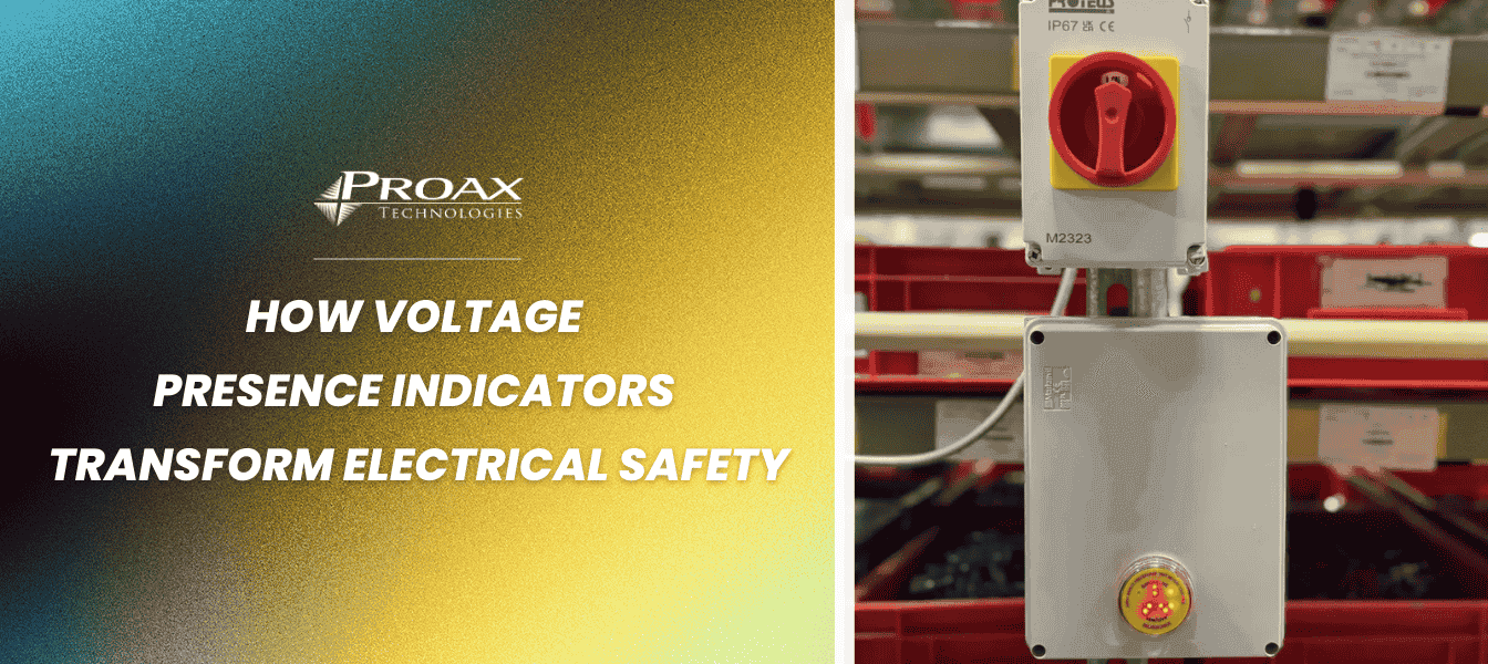
The REMLIVE RL-24i Isolator Check provides the user with a positive check when isolating plant. It provides electrical isolation between the DIN rail unit and the door mounted display unit. This fundamental safety function eliminates dangerous assumptions about electrical status during maintenance procedures.
The door unit is designed to fit through the front of a control panel or switch so the user can see a live/isolation status. The super bright REMLIVE RL-24i display provides the user with a quick and easy method of proof of isolation in lock out / tag out procedures.
Isolator Check vs Phase Indicator – Main Differences
While both devices serve essential safety functions, they address different monitoring needs:
Isolator Check Features:
* Maximum Rated Current 20mA
* AC Voltages (50/60Hz) (Continuous) Min 24 Max 1,000
* DC Voltages (Continuous) Min 26 Max 1,000
* Multiple connection configurations including single phase, three phase, and neutral combinations
Phase Indicator Specifications:
* 3 Phase & Earth and 3 Phase, Neutral & Earth connections
* AC Voltages (50/60Hz) (Continuous) Min 24 Max 1,000
* Dedicated phase rotation monitoring with directional indicators
Voltage Handling and Safety Features
Both devices are engineered for demanding industrial environments. The input circuit is designed to withstand transient overvoltages according to measurement category IV. The equipment should not be subjected to transient overvoltage exceeding 8kV L-E.
Safety protection includes:
* The REMLIVE RL-24i has embedded 500mA fuse protection up stream of internal surge suppression
* For DC applications external 500mA Time Delay fuses rated to the voltage application shall be used
* Robust measurement category IV rating for industrial applications
Feature
Isolator Check
Phase Indicator
Supports AC Applications
✓
✓
Supports DC Applications
✓
—
Maximum Current of 20mA
✓
✓
Built-in Fuse Link
✓
✓
Phase Rotation Detection
—
✓
Single Phase Monitoring
✓
—
Neutral Monitoring
✓
✓
Voltage Range (24V-1000V)
✓
✓
← Scroll horizontally to view more →
Installing Remlive with Ease
To mechanically install REMLIVE RL-24i simply clip the Main Panel Unit onto Din Rail (Top Hat). Fit Door Unit via 30.5mm hole, secure with locking nut and plug the RJ45 connector into the Main Panel Unit front fascia socket.
Installation requirements include:
* The equipment shall be connected to the supply using suitable wiring of at least 1mm2, with insulation rated to the voltage of the system being monitored
* A suitable disconnect device shall be installed in a location readily accessible and visible to the user
Dimensions:
* DIN Rail Module 22.5mm (W) x 100mm (H) x 122mm (D)
* Door Display Unit 30.5mm mounting hole diameter. The indicator unit itself measures 57mm (Deep) x 26mm (Rear Diameter) / 41mm (Front Diameter)
* Weight 232g total weight per RL-24i unit
Small Footprint, Strong Ingress Protection
The REMLIVE RL-24i series delivers maximum protection in a compact design. REMLIVE RL-24i is housed in a robust UL94 V-0 flame retardant enclosure, which has been selected for its durability and protective, insulation and zero halogen properties.
Protection specifications:
* REMLIVE RL-24i Door Unit has been designed to meet with IP66 requirements
* This equipment is tested and certified for use at ambient temperature between -35°C to 55°C and below 5000m altitude
Key Benefits of Remlive
The REMLIVE RL-24i series offers several critical advantages for industrial safety:
Enhanced Isolation Procedures REPLACE the REMLIVE RL-24i unit if EITHER of the two sets of TWO FLASHING INDICATORS FAIL TO FLASH ONCE A SECOND when a live supply is connected, unless they have been deliberately switched to the OFF position
Comprehensive Phase Monitoring The Phase Indicator provides detailed status information through its LED display system. The banks of two light emitting diodes at either side of the door unit will flash if the RL-24i Phase Indicator detects the correct cyclic phase rotation sequence.
Flexible Configuration Options Available configurations support diverse installation requirements, from simple single-phase monitoring to complex three-phase systems with neutral monitoring.
The REMLIVE RL-24i Isolator Check (part number RL-24i-IC-23) provides comprehensive voltage monitoring with up to 690VAC Cat IV configurations and compliance with IEC 60204 standards.
For phase sequence monitoring, the REMLIVE Phase Indicators are available in both Clockwise and Anti-Clockwise configurations, ensuring proper rotational verification for three-phase equipment.
These devices represent essential safety equipment for any facility where electrical maintenance occurs, providing the visual confirmation necessary to prevent accidents and ensure regulatory compliance. Through their robust design and reliable operation, they serve as critical components in comprehensive electrical safety programs.
Questions & Answers of Remlive
What is the purpose of a presence of voltage indicator?
A presence of voltage indicator provides a clear visual indication that a circuit is live. This helps operators reduce the risk of exposure to hazardous voltage, improve electrical safety, and increase workplace efficiency.
How does the REMLIVE RL-24i Isolator Check work?
The RL-24i Isolator Check alerts users to the presence of voltage, showing live indication immediately before isolating and no indication immediately after isolating. This makes it valuable for electrical isolation procedures.
What is the difference between the RL-24i Isolator Check and the RL-24i Phase Indicator?
While both devices look similar, they have different functions. The Isolator Check shows if a circuit is live, while the Phase Indicator confirms phase rotation and correct sequencing of electrical phases.
Can the RL-24i devices be used for DC voltage applications?
The Isolator Check supports AC and DC voltages up to 1000V. The Phase Indicator only supports AC voltage and does not support DC applications.
What industries use presence of voltage indicators?
These devices are used in a wide range of industries, including power stations, coal mines, automated warehouses, nuclear facilities, and even particle accelerator sites.
What safety features do the RL-24i devices have?
They are designed to withstand transient overvoltages, include an embedded 500mA fuse link for surge protection, and have electrical separation between the DIN rail unit and the door-mounted display to keep dangerous voltages inside the cabinet.
How easy is it to install the RL-24i?
Installation is quick and simple for a competent person following local electrical regulations. The DIN rail-mounted panel unit connects to the door unit using an RJ45 cable, with no special tools required.
What is the maximum distance between the RL-24i main unit and door unit?
The standard cable length provided is 1.4m, but the distance can be extended up to 10m using a standard RJ45 Ethernet patch cable.
What ingress protection does the RL-24i have?
The door unit is rated IP66 for high protection against dust and water, while the main panel unit should be installed inside an enclosure with an IP rating suitable for the environmental conditions of the site.
How do presence of voltage indicators enhance electrical safety?
They provide clear, reliable visual confirmation of voltage presence or phase rotation, helping to prevent accidental contact with live circuits, improve isolation procedures, and minimise downtime.
PneumaticsSMC's EX600 Series: Integrated Safety Communication Fieldbus System
Aug 13, 2025|
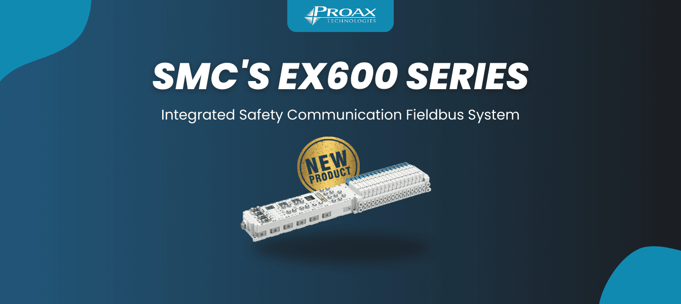
SMC's new EX600 Series Safety Communication Fieldbus System combines safety and general-purpose I/O into one manifold, addressing the complexity of managing separate systems in industrial automation. This system supports EtherNet/IP™ and CIP Safety™ protocols while meeting IEC 61508/IEC 62061 SIL3 and ISO 13849 PL e safety standards. As an elite distributor of SMC, Proax is proud to offer this innovative solution to our customers.
Key Features
Unified Integration
Safety and general-purpose I/O modules work together in the same manifold, reducing footprint and simplifying wiring.
Advanced Safety Output
Three dedicated safety outputs with redundant safety switches (24V and 0V sides) provide continuous diagnostic monitoring. If an abnormality is detected, the system automatically transitions to a safe state.
Flexible Safety Input
Connect up to 16 safety devices like residual pressure exhaust valves, position sensors, and laser curtains with two configuration options:
* Single Input (1oo1): 16 Safety Inputs (SIL2, PL d)
* Dual Input (1oo2): 8 Safety Inputs (SIL3, PL e)
Direct Configuration
Configure the system directly on the Fieldbus module without requiring a PLC or PC, streamlining setup and maintenance.
Safety Certifications
The EX600 Series is certified by TÜV SÜD and complies with functional safety standards IEC 61508/IEC 62061 SIL 3 and ISO 13849-1 PL e. This certification ensures the system meets the highest safety integrity levels for industrial applications.
SIL (Safety Integrity Level) - Defined by international standard IEC 61508/IEC 62061, with safety levels from SIL 1 to 4, where SIL 1 is the lowest and SIL 4 is the highest.
PL (Performance Level) - Specified by international standard ISO 13849, with safety levels from PL a to PL e, where PL a is the lowest and PL e represents the highest safety function capability.
Available Models
Model
Safety Inputs
Safety Outputs
Max. Solenoids
Compatible Valve Series
EX600-FV□1
16
1 for valves, 2 for external devices
32
JSY, SY, VQC
EX600-FV□2
16
1 for valves, 2 for external devices
128
JSY3000-L/P, IITV23
← Scroll horizontally to view more →
System Components
Fieldbus Module: Handles network communication with built-in display for local monitoring and configuration.
Safety Input/Output Module: Manages safety-critical functions while maintaining international safety standard compliance.
General Purpose I/O Module: Handles standard digital operations with up to 9 modules configurable in any order.
Frequently Asked Questions
Is it possible to mount a terminating resistor to an SI unit?
Yes, you can mount a terminating resistor to an SI unit. For detailed instructions, refer to the operation manual on the SMC website. The SI unit part number (EX□-□) is determined by your valve manifold model - check the valve catalog for corresponding SI unit part numbers.
Download Catalog
What is the correspondence between the SI unit output number and the valve coil?
The output number refers to the D-side solenoid position on the manifold, starting at zero. When the A/B piping port faces you, the D side is on your left. For standard double solenoid manifolds, output numbers are assigned from A side to B side. Single valves leave the B side output empty. For special wiring specification manifolds, check the individual specification sheet.
Have More Questions or Ready to Order?
The EX600 Series will be available on our website shortly. If you have additional questions about the system or would like to place an order, contact our team today for expert guidance on configuration options for your specific application.

Food and BeverageStop Costly Mislabeling Before It Starts: Smart Label Roll Verification for Food Packaging
Aug 1, 2025|
A single mislabeled product can trigger an FDA investigation, force a costly recall, and damage your brand reputation. In food and consumer goods packaging, getting the label right isn't just about quality—it's about protecting your business from million-dollar mistakes.
The solution? Automated label roll verification that catches errors before the first product is ever labeled.
The Hidden Cost of Manual Label Checking
Most food manufacturers still rely on visual inspection to catch labeling errors. But human inspectors can't keep up with modern production speeds, and they miss critical issues like:
* Subtle barcode quality problems that cause scanning failures
* Template mismatches in multi-language packaging
* Orientation errors that lead to upside-down labels
* Pre-printed content that doesn't match the current batch
By the time these errors are discovered, thousands of products may already be mislabeled.
How Smart Verification Works
Modern label roll verification systems check everything before production starts:
Pre-Production Verification: The system confirms the correct roll type, verifies pre-printed content matches templates, and validates barcode quality—all before the roll enters the printer.
Loading Accuracy: Sensors confirm operators have loaded the right roll in the correct orientation, preventing simple but costly setup errors.
Real-Time Monitoring: Throughout production, continuous machine vision inspection catches printing issues immediately and stops the line automatically when problems occur.
Verification Stage What Gets Checked Technology Used Benefit Pre-Load Check Roll type, content, barcode quality MV-4000 Vision System Prevents wrong rolls from entering production Loading Verification Proper placement, orientation NX1 Controller + Sensors Ensures correct setup before printing starts In-Line Monitoring Print quality, template matching Integrated Vision + Control Catches errors immediately during production Data Logging Batch tracking, quality metrics NX1 + MES Integration Enables full traceability and compliance reporting
← Scroll horizontally to view more →
Proven Results in Food Manufacturing
Major Food Producer Success
Working with Omron, a leading food manufacturer implemented Omron's V275 inspection system and achieved near-zero mislabeled products while handling multi-language formats seamlessly.
Food Packaging Equipment Manufacturer
A major equipment manufacturer in the food packaging industry leveraged Sysmac solutions to set new benchmarks for machine performance, achieving faster setup times, reduced waste, and improved overall equipment efficiency through advanced data capabilities and seamless integration.
Download Success Story
The Technology Behind Smart Verification
NX1 Series Controllers: High-speed edge controllers like the NX102 and NX1P that integrate logic, motion, safety, and data connectivity in one unit. With 1ms cycle times, they provide instant response to quality issues.
MV-4000 Smart Cameras: Industrial vision systems capable of inspecting 4,000-14,000 parts per minute, handling barcode verification, text recognition, and layout checks simultaneously.
Sysmac Platform: Unified development environment that enables rapid format changeovers—template switches happen in under a minute for multi-SKU production runs.
Check Omron Sensors & Machine Vision
Why Automation Wins
Speed: Inspects at full production speed without creating bottlenecks
Consistency: Maintains the same high standards across all shifts
Compliance: Automatically logs data for FDA, CFIA, and ISO requirements
Flexibility: Handles multiple languages and formats with quick changeovers
ROI That Makes Sense
The cost of implementing label verification is typically recovered within months through:
* Prevented recalls and associated costs
* Reduced waste from mislabeled products
* Improved throughput from automated inspection
* Lower labor costs for quality control
Consider that a single recall can cost millions in direct expenses plus immeasurable brand damage—making verification systems one of the smartest investments in food packaging.
Ready to Eliminate Labeling Errors?
At Proax Technologies, we've helped food and consumer goods manufacturers across North America implement bulletproof labeling systems. From assessment through installation, we ensure your verification system delivers maximum protection and ROI.
Contact our automation experts to discuss how label roll verification can protect your brand and streamline your packaging operations.