










































Robotics|Automation|Published Oct 15, 2026|Updated Oct 15, 2026|4 MIN READ
How to Choose a Robotic Tool Changer: 7 Questions Engineers Should Ask

To choose a robotic tool changer, size it for the moment load of your heaviest tool, not for payload alone. Then confirm that it passes the air, power and signals each tool needs, stays locked if air pressure is lost, repeats accurately enough for the process, and fits your robot flange, storage layout and environment.
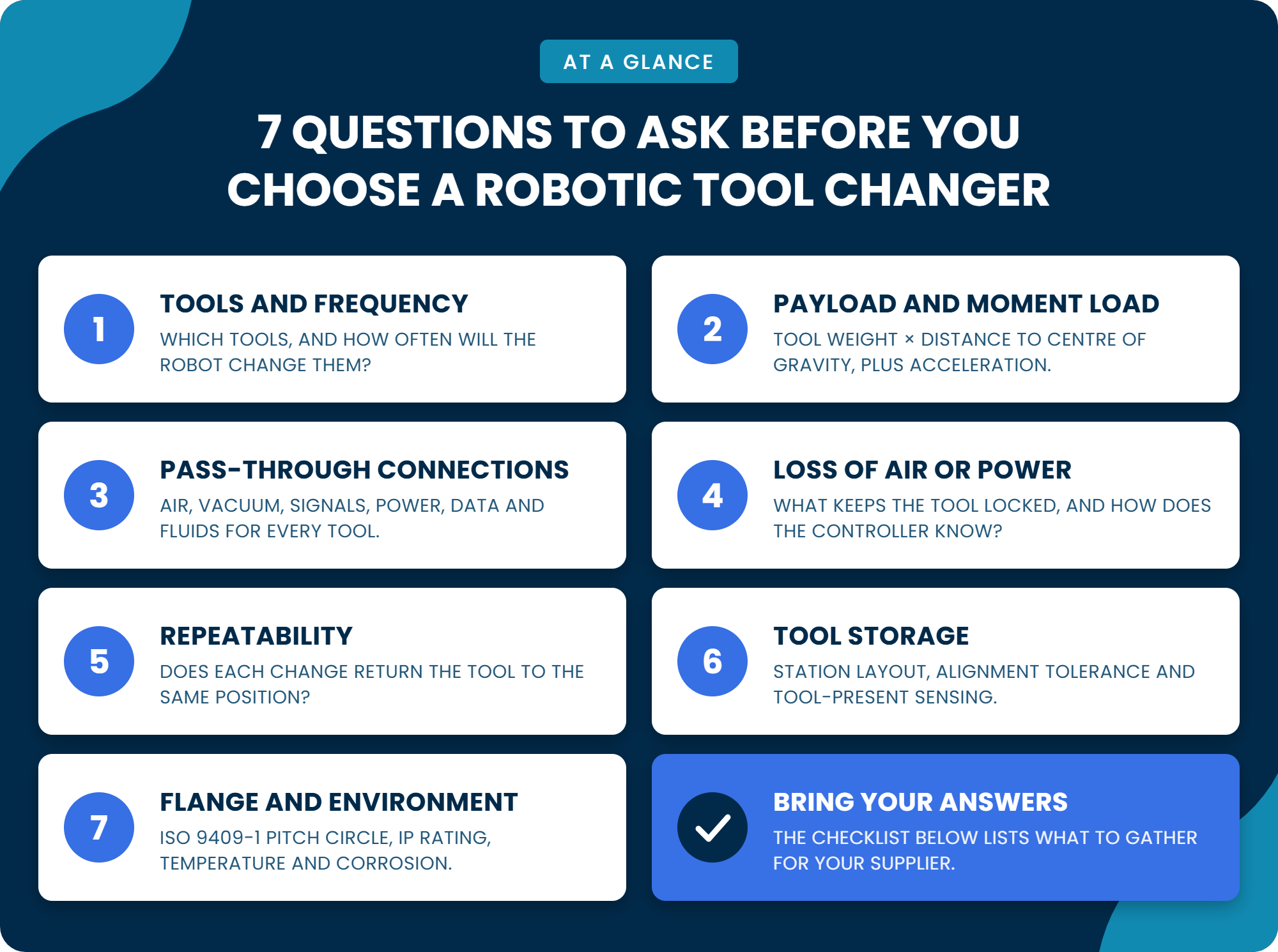
1. What Tools Will the Robot Change, and How Often?
List every end effector the robot will carry: grippers, vacuum tooling, screwdrivers, dispensing heads. Include tools planned for later, because the changer is sized for the worst case.
Then estimate changes per shift and compare your yearly count with the rated life.
A changer swapping every cycle builds up cycles far faster than one used only for changeovers.
2. What Payload and Moment Load Must It Carry?
Robot tool changer payload is only the starting point. The number that decides the size is moment load: tool weight multiplied by the distance from its centre of gravity to the coupling face.
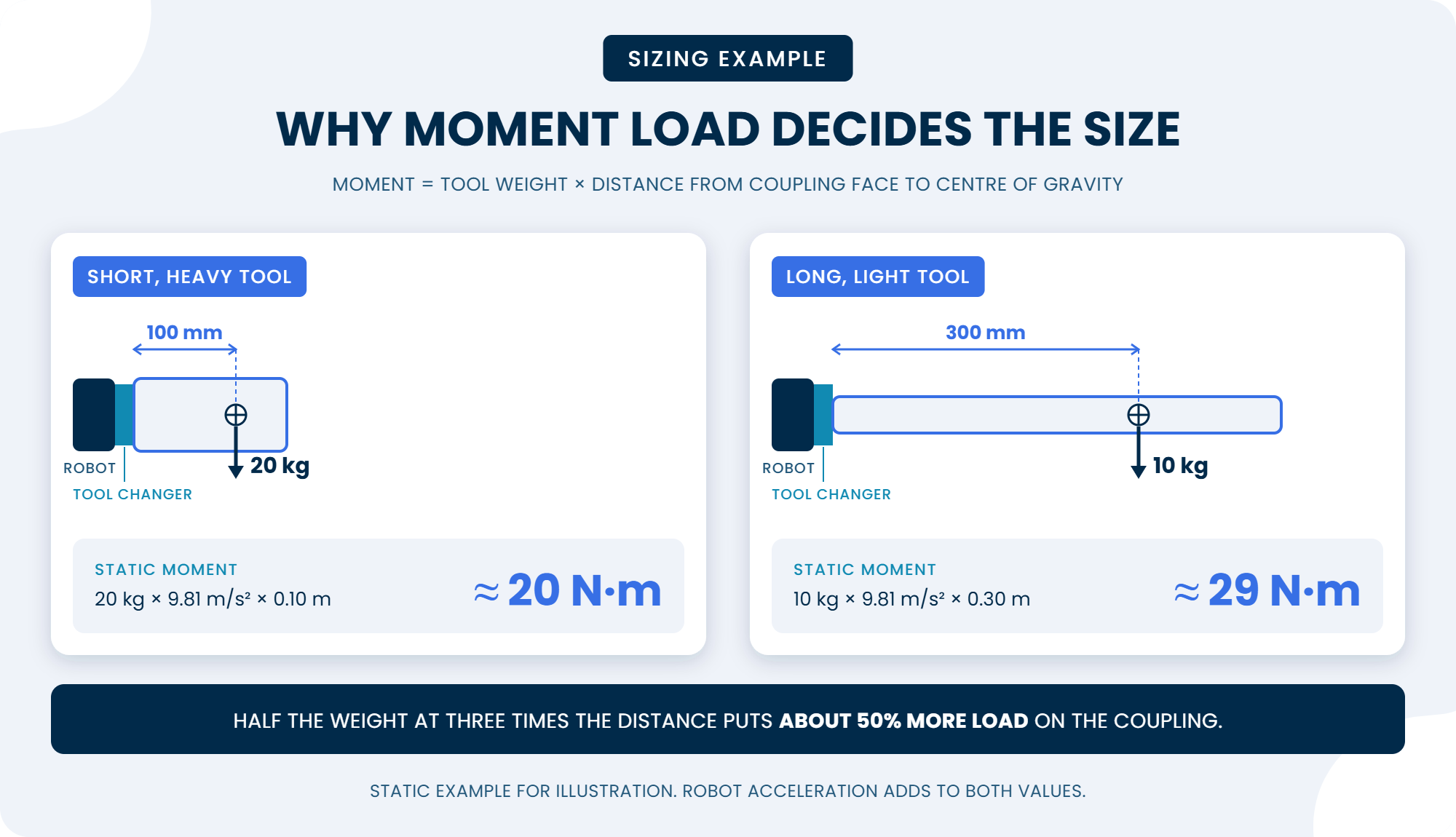
Calculate the moment for your heaviest or longest tool, then check the conditions behind any payload rating, since ratings assume a stated acceleration and centre-of-gravity offset. To see payload by flange size, review Zimmer WPR5000 sizes and features.
Rule of Thumb
Allow two to three times the static moment to cover robot motion.
3. What Air, Power, Signals or Fluids Must Pass Through?
Air and Vacuum
Compressed air and vacuum, with the flow each tool requires.
Sensor and I/O Signals
Tool-present, gripper position and other inputs and outputs.
Power
For electric grippers or servo tools.
Fieldbus or Ethernet
Communication for smart tools and I/O modules.
Hydraulics or Coolant
Fluid lines for tools that need them.
Spare Capacity
Check which are built in and which need add-on modules, and leave room to grow.
4. What Happens if Air Pressure or Power Is Lost?
Many units are pneumatic tool changers, so ask what holds the tool when air fails or an emergency stop vents the system. Look for a mechanical lock that holds without pressure.
Then ask how the controller knows the coupling state.
Locked
The coupling is closed and holding the tool.
Unlocked
The coupling is open and ready to release or pick up.
Tool Present
A tool is seated on the coupling.
With all three signals, the program can refuse to move on a bad connection.
If your risk assessment calls for a performance level, confirm which options it depends on.
5. What Repeatability Does the Process Need?
Each change must return the tool to the same position. Compare the stated repeatability with your process tolerance, and ask about rigidity, because a coupling that flexes under load shifts the tool point.
6. How Will Idle Tools Be Stored and Picked Up?
Tools not in use sit in a storage station, also called a tool stand. Check the approach path, the misalignment the station tolerates at pick-up and whether sensors confirm a tool is present.
7. Does It Fit the Robot Flange and the Environment?
Many industrial robot flanges follow ISO 9409-1, which defines the bolt pattern by pitch circle diameter. A changer with the same pitch circle mounts directly; a mismatch needs an adapter plate, which adds height and weight. Then match the IP rating and temperature range to the cell.
Where the Zimmer WPR5000 Fits
The Zimmer WPR5000 is a pneumatic robot end-effector changer. It may suit cells that need the tool held if air is lost, repeatable positioning and an ISO-pattern flange. Explore the Zimmer WPR5000 tool changer, then click Get Custom Quote to request datasheets and pricing.
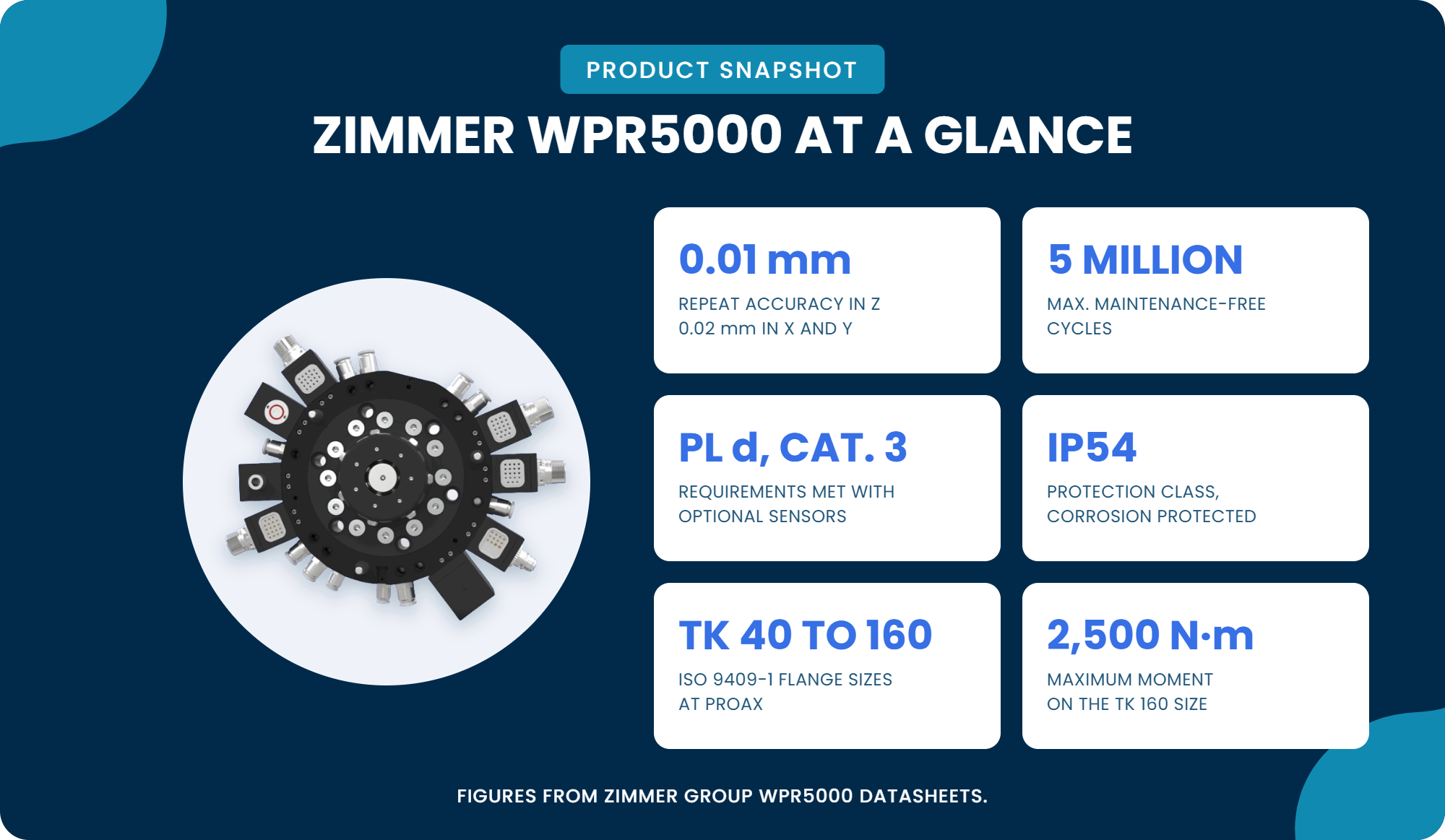
Moment Load
Flat design reduces flange torque. Maximum moments from 100 n·m (TK 40) to 2,500 n·m (TK 160).
Pass-Through
Four to ten built-in air feed-throughs, plus optional energy elements for signals, power and hydraulics.
Loss of Air
A spring-loaded, self-locking piston keeps the tool attached when air is lost.
Safety Level
Meets Performance Level d, category 3 requirements with optional sensors.
Repeatability
0.01 Mm in Z, 0.02 mm in X and Y.
Flange and Environment
EN ISO 9409-1 mounting, TK 40 to TK 160. IP54, corrosion protected.
Source: Zimmer Group WPR5000 datasheets.
Checklist: What to Gather Before You Contact a Supplier
Robotic Tool Changer Selection Goes Faster With This Information:
Ready to Size Your Tool Changer?
Bring your checklist to Proax for application support from our in-house engineers.