


2700588
SKU
PHX2700588
MPN
PSR-PC40-2NO-1DO-24DC-SC
Weight
0.208 kg
Series PSR-PC
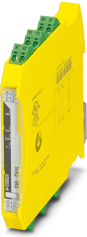
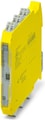
PSR-PC40-2NO-1DO-24DC-SC - Coupling relay
Coupling relay for SIL 3 high- and low-demand applications, couples digital output signals to the I/O, 2 enabling current paths, 1 digital signal output, safe state off applications, test pulse filter, plug-in screw terminal block
- Up to SIL 3 in accordance with IEC 61508
- Force-guided contacts in accordance with EN 50205
- Easy proof test according to IEC 61508 thanks to integrated signal contact
- Approved for Class I, Zone 2 applications
- Low housing width of just 12.5 mm
- Manually monitored and automatic activation in a single device
- Self-regulation with device-internal lock
- Long service life thanks to filtering of controller test pulses
- 2 enabling current paths, 1 digital signal output
- Couples digital output signals from failsafe controllers to I/O devices (valves, etc.) for electrical isolation and power adaptation
- Corrosion protection through protective coating on the PCB
Technical Specifications
Utilization restriction
| CCCex note | Use in potentially explosive areas is not permitted in China. |
Product properties
| Product family | PSRmini |
| Application | Safe switch off |
| Application | High demand |
| Application | Low demand |
| Application | Ex |
| Relay type | Electromechanical relay with force-guided contacts in accordance with IEC/EN 61810-3 |
Times
| Typ. starting time with Us | < 200 ms (when controlled via A1, automatic start) |
| Typical release time | < 35 ms (when controlled via A1) |
| Recovery time | 500 ms |
Electrical properties
| Maximum power dissipation for nominal condition | 5.5 W (IL² = 60 A²) |
| Nominal operating mode | 100% operating factor |
Air clearances and creepage distances between the power circuits
| Rated Insulation Voltage | 250 V AC |
| Rated surge voltage/insulation | Safe isolation, 6 kV reinforced insulation from control circuit, start circuit, signal output to the enabling current paths, 4 kV/basic insulation between the enabling current paths and between all current paths and housing |
Supply
| Designation | A1/A2 |
| Rated control circuit supply voltage US | 20.4 V DC ... 26.4 V DC |
| Rated control circuit supply voltage US | 24 V DC -15 % / +10 % (A1/A2) |
| Rated control supply current IS | typ. 75 mA (depending on load M1 +100 mA) |
| Power consumption at US | typ. 1.8 W |
| Inrush Current | typ. 400 mA (Δt < 100 µs at Us) |
| Filter time | max. 2 ms (at A1-A2; test pulse width) |
| Filter time | ≥ 100 ms (at A1-A2; test pulse rate) |
| Protective circuit | Serial protection against polarity reversal; 33 V suppressor diode |
Digital: Start circuit (Y1, Y2)
| Number of Inputs | 2 (Non-safety-related start inputs: Y1/Y2) |
| Inrush Current | < 10 mA |
| Max. permissible overall conductor resistance | 150 Ω |
| Voltage at input/start and feedback circuit | 24 V DC -15 %; +10 % |
| Current consumption | < 5 mA |
Relay: Enabling current paths (13/14, 23/24)
| Output description | 2 NO contacts each in series, without delay, floating |
| Number of Outputs | 2 (safety-related N/O contacts: 13/14, 23/24) |
| Contact switching type | 2 enabling current paths |
| Contact Material | AgSnO2 |
| Switching voltage | min. 12 V AC/DC |
| Switching voltage | max. 250 V AC/DC (Observe the load curve) |
| Switching capacity | min. 60 mW |
| Inrush Current | min. 3 mA |
| Inrush Current | max. 6 A |
| Switching capacity in accordance with IEC 60947-5-1 | 4 A (24 V (DC13)) |
| Switching capacity in accordance with IEC 60947-5-1 | 5 A (250 V (AC15)) |
| Limiting Continuous Current | 6 A (High demand) |
| Limiting Continuous Current | 4 A (Low demand) |
| Sq. Total current | 60 A2 (observe derating) |
| Switching frequency | max. 0.5 Hz |
| Mechanical service life | 10x 10⁶ cycles |
| Output fuse | 6 A gL/gG |
| Output fuse | 4 A gL/gG (for low-demand applications) |
Signal: M1
| Output description | PNP |
| Number of Outputs | 1 (non-safety-related) |
| Voltage | approx. 22 V DC (Us - 2 V) |
| Current | max. 100 mA |
| Maximum Inrush Current | 500 mA (Δt = 1 ms at Us) |
| Short-circuit protection | no |
| Output fuse | 150 mA fast blow |
Connection technology
| pluggable | yes |
Conductor connection
| Connection Method | Screw connection |
| Conductor cross section rigid | 0.2 mm² ... 2.5 mm² |
| Conductor cross section flexible | 0.2 mm² ... 2.5 mm² |
| Conductor cross-section AWG | 24 ... 12 |
| Stripping length | 7 mm |
| Screw thread | M3 |
| Tightening torque | 0.5 Nm ... 0.6 Nm |
Signaling
| Status display | 2 x green LEDs |
| Operating voltage display | 1 x yellow LED |
| Error indication | 1 x red LED |
Dimensions
| Width | 12.5 mm |
| Height | 112.2 mm |
| Depth | 114.5 mm |
Material specifications
| Color (Housing) | yellow (RAL 1018) |
| Housing Material | Polyamide |
Safety data
| Stop category | 0 |
Safety data: EN 50156
| Safety Integrity Level (SIL) | 3 |
Safety data: IEC 61508 - High demand
| Safety Integrity Level (SIL) | 3 |
Safety data: IEC 61508 - Low demand
| Safety Integrity Level (SIL) | 3 |
Ambient conditions
| Degree of Protection | IP20 |
| Min. degree of protection of inst. location | IP54 |
| Ambient Temperature (Operation) | -40 °C ... 70 °C (observe derating) |
| Ambient temperature (storage/transport) | -40 °C ... 85 °C |
| Maximum altitude | ≤ 2000 m (Above sea level) |
| Max. permissible humidity (storage/transport) | 75 % (on average, 85% infrequently, non-condensing) |
| Max. permissible relative humidity (operation) | 75 % (on average, 85% infrequently, non-condensing) |
| Shock | 15g |
| Vibration (Operation) | 10 Hz ... 150 Hz, 2g |
ATEX
| Identification | II 3G Ex ec nC IIC T4 Gc |
| Certificate | UL 22 ATEX 2912X |
IECEx
| Identification | Ex ec nC IIC T4 Gc |
| Certificate | IECEx UL 22.0037X |
UL, USA/Canada
| Identification | cULus |
| Certificate | E140324 |
UL Ex, USA / Canada
| Identification | Class I, Zone 2, AEx nA nC IIC T4 / Ex nA nC IIC Gc T4 X |
| Identification | Class I, Div. 2, Groups A, B, C, D, T4 |
| Certificate | E360692 |
CE
| Identification | CE-compliant |
Environmental simulation test
| Identification | G3 |
| Certificate | ISA-S71.04 |
CCC / China-Ex
| Identification | Ex ec nC IIC T4 Gc |
| Certificate | 2022122304115695 |
DNV
| Identification | C, EMC2 |
| Certificate | 11253-14 HH |
Air clearances and creepage distances between the power circuits
| Standards/regulations | EN 60664-1, EN 60079-7, EN 60079-15 |
Mounting
| Mounting Type | DIN rail mounting |
| Assembly instructions | See derating curve |
| Mounting Position | vertical, horizontal, with front of module upward |
Why Proax for Phoenix Contact 2700588?
Proax is an authorized distributor of Phoenix Contact 2700588 and one of Phoenix Contact's largest distributors in North America. Our highly skilled in-house technical team is ready to assist with any technical needs.
Have a question in mind? to help you get the right product as quickly as possible for your project. We're always here to help!
Short Lead Time
Highly Trained Staff
Live Chat
Technical Support
Local Inventory
60+ Years Experience
Additional Information
| Pack Size | 1 |
Recommended

 PSR-PC40-2NO-1DO-24DC-SP - Coupling relay for SIL 3 high and low-demand applications, couples digital output signals to the I/O, 2 enabling current paths, 1 digital signal output, safe state off applications, test pulse filter, pluggable Push-in terminal block
 PSR-PC50-1NO-1DO-24DC-SC - Coupling relay for SIL 3 low demand applications, couples digital output signals to the periphery, 1 enabling current path, module for F&G applications, test pulse filter, plug-in screw connection, 17.5 mm width
- PSR-PC50-1NO-1DO-24DC-SP - Coupling relay for SIL 3 low-demand applications, couples digital output signals to the I/O, 1 enabling current path, module for F&G applications, test pulse filter, width: 17.5 mm, pluggable Push-in terminal block
 PSR-PC51-1NO-1NC-24DC-SC - Coupling relay for electrical isolation and power adaptation for SIL 3 F&G applications, low demand, load diagnostics in the Off and On state for wire break and short circuit, 1 enabling current path, test pulse filter, plug-in screw terminal block, width: 17.5 mm
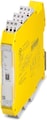 PSR-PC51-1NO-1NC-24DC-SP - Coupling relay for electrical isolation and power adaptation for SIL 3 F&G applications, low demand, load diagnostics in the Off and On state for wire break and short circuit, 1 enabling current path, test pulse filter, plug-in Push-in terminal block, width: 17.5 mm
 PSR-PC32-2NO-1NC-24-230UC-SC - Coupling relay for SIL 3 high and low-demand applications, couples digital signals to the I/O, 24 V ... 230 V wide-range input, 2 enabling current paths (1x up to 60 V, 1x up to 250 V) 1 confirmation current path, safe state off applications, plug-in screw terminal block
- PSR-PC32-2NO-1NC-24-230UC-SP - Coupling relay for SIL 3 high and low-demand applications, couples digital signals to the I/O, 24 V ... 230 V wide-range input, 2 enabling current paths (1x up to 60 V, 1x up to 250 V) 1 confirmation current path, safe state off applications, pluggable Push-in terminal block
 PSR-PC52-1NO-1NC-24DC-SC - Coupling relay for electrical isolation and power adaptation for SIL 3 F&G applications, low demand, load diagnostics in the Off and On state for wire break and short circuit, 1 enabling current path, test pulse filter, plug-in screw terminal block, width: 17.5 mm
 PSR-PC52-1NO-1NC-24DC-SP - Coupling relay for electrical isolation and power adaptation for SIL 3 F&G applications, low demand, load diagnostics in the Off and On state for wire break and short circuit, 1 enabling current path, test pulse filter, plug-in Push-in terminal block, width: 17.5 mm
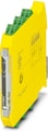 Coupling relay for SIL 3 high- and low-demand applications, couples digital output signals to the periphery, 1 enabling current path, 1 confirmation current path, 1 digital signal output, safe state off applications, test pulse filter, TBUS connection, plug-in screw terminal block
- PSR-PC20-1NO-1NC-24DC-SP - Coupling relay for SIL 3 high- and low-demand applications, couples digital output signals to the periphery, 1 enabling current path, 1 confirmation current path, 1 digital signal output, safe state off applications, test pulse filter, TBUS connection, pluggable Push-in terminal block
 PSR-PC21-2NO-2NC-24DC-SC - Coupling relay for SIL 3 high and low-demand applications, coupled digital output signals to the I/O, 2 independently controllable enabling current paths, 2 confirmation current paths, safe state off applications, test pulse filter, pluggable screw terminal block
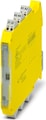 PSR-PC21-2NO-2NC-24DC-SP - Coupling relay for SIL 3 high and low-demand applications, coupled digital output signals to the I/O, 2 independently controllable enabling current paths, 2 confirmation current paths, safe state off applications, test pulse filter, pluggable Push-in terminal block