3211485
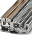
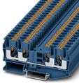
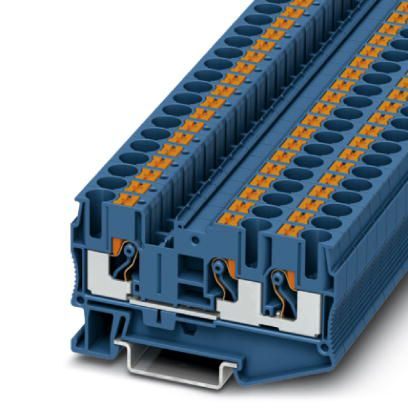
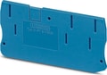
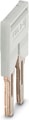
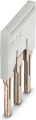
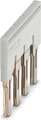
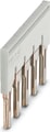
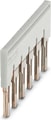
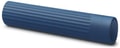
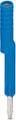
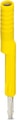
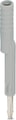
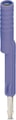
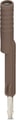
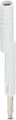
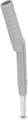
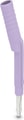
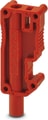
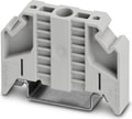
PT 6-TWIN BU - Feed-through terminal block
Feed-through terminal block, nom. voltage: 1000 V, nominal current: 41 A, number of connections: 3, connection method: Push-in connection, Rated cross section: 6 mm2, cross section: 0.5 mm2 - 10 mm2, mounting type: NS 35/7,5, NS 35/15, color: blue
- The Push-in connection terminal blocks are characterized by the system features of the CLIPLINE complete system and by easy and tool-free wiring of conductors with ferrules or solid conductors
- The compact design and front connection enable wiring in a confined space
- In addition to the testing option in the double function shaft, all terminal blocks provide an additional test pick-off
- Tested for railway applications
PT
The Phoenix Contact PT Series comprises feed-through terminal blocks that utilize Push-in connection technology, offering efficient and reliable wiring solutions for various industrial applications. These terminal blocks are designed for straightforward conductor insertion, enhancing installation speed and ensuring secure connections.
- Push-in Connection Technology: The PT Series employs a direct plug-in method, allowing solid conductors or conductors with ferrules to be inserted easily without the need for tools. This design facilitates quick and reliable wiring.
- Compact Design: The terminal blocks feature a space-saving form factor, making them suitable for applications where installation space is limited.
- High Electrical Ratings: Depending on the specific model, the PT Series terminal blocks can handle nominal voltages up to 800 V and nominal currents up to 32 A, accommodating a wide range of electrical requirements.
- Versatile Conductor Compatibility: These terminal blocks support various conductor types and sizes, providing flexibility in wiring configurations.
- Integration with CLIPLINE Complete System: The PT Series is compatible with Phoenix Contact's CLIPLINE complete system, allowing for standardized bridging, marking, and testing accessories, which simplifies inventory management and enhances system modularity.
General
| Number of rows | 1 |
| Number of Connections | 3 |
| Potentials | 1 |
| Nominal cross section | 6 mm² |
| Color | blue |
| Insulating material | PA |
| Flammability rating according to UL 94 | V0 |
| Area of application | Railway industry |
| Area of application | Machine building |
| Area of application | Plant engineering |
| Mounting Type | NS 35/7,5 |
| Rated surge voltage | 8 kV |
| Degree of pollution | 3 |
| Overvoltage category | III |
| Insulating material group | I |
| Maximum power dissipation for nominal condition | 1.31 W |
| Maximum Load Current | 52 A (for a 10 mm² rigid conductor cross section, the maximum load current must not be exceeded by the total current of all connected conductors.) |
| Nominal current IN | 41 A |
| Nominal voltage UN | 1000 V |
| Open side panel | Yes |
| Shock protection test specification | DIN EN 50274 (VDE 0660-514):2002-11 |
| Back of the hand protection | guaranteed |
| Finger protection | guaranteed |
| Result of surge voltage test | Test passed |
| Surge voltage test setpoint | 9.8 kV |
| Result of power-frequency withstand voltage test | Test passed |
| Power frequency withstand voltage setpoint | 2.2 kV |
| Result of the test for mechanical stability of terminal points (5 x conductor connection) | Test passed |
| Result of flexion and pull-out test | Test passed |
| Bending test rotation speed | 10 rpm |
| Bending test turns | 135 |
| Bending test conductor cross section/weight | 0.5 mm² / 0.3 kg |
| Bending test conductor cross section/weight | 6 mm² / 1.4 kg |
| Bending test conductor cross section/weight | 10 mm² / 2 kg |
| Tensile test result | Test passed |
| Conductor cross section tensile test | 0.5 mm² |
| Tractive force setpoint | 20 N |
| Conductor cross section tensile test | 6 mm² |
| Tractive force setpoint | 80 N |
| Conductor cross section tensile test | 10 mm² |
| Tractive force setpoint | 90 N |
| Result of tight fit on support | Test passed |
| Tight fit on carrier | NS 35 |
| Setpoint | 5 N |
| Result of voltage-drop test | Test passed |
| Requirements, voltage drop | U1 ≤ 3.2 mV; U2 ≤ 1.5 x U1 |
| Result of temperature-rise test | Test passed |
| Requirement temperature-rise test | Increase in temperature ≤ 45 K |
| Note | The max. load current must not be exceeded by the total current of all connected conductors. |
| Short circuit stability result | Test passed |
| Conductor cross section short circuit testing | 6 mm² |
| Short-time current | 0.72 kA |
| Conductor cross section short circuit testing | 6 mm² |
| Short-time current | 0.72 kA |
| Result of thermal test | Test passed |
| Proof of thermal characteristics (needle flame) effective duration | 30 s |
| Result of aging test | Test passed |
| Ageing test for screwless modular terminal block temperature cycles | 192 |
| Oscillation, broadband noise test result | Test passed |
| Test specification, oscillation, broadband noise | DIN EN 50155 (VDE 0115-200):2008-03 |
| Test spectrum | Service life test category 2, bogie-mounted |
| Test frequency | f1 = 5 Hz to f2 = 250 Hz |
| ASD level | 6.12 (m/s²)²/Hz |
| Acceleration | 3.12g |
| Test duration per axis | 5 h |
| Test directions | X-, Y- and Z-axis |
| Shock test result | Test passed |
| Test specification, shock test | DIN EN 50155 (VDE 0115-200):2008-03 |
| Shock form | Half-sine |
| Acceleration | 30g |
| Shock duration | 18 ms |
| Number of shocks per direction | 3 |
| Test directions | X-, Y- and Z-axis (pos. and neg.) |
| Relative insulation material temperature index (Elec., UL 746 B) | 130 °C |
| Temperature index of insulation material (DIN EN 60216-1 (VDE 0304-21)) | 130 °C |
| Static insulating material application in cold | -60 °C |
| Surface flammability NFPA 130 (ASTM E 162) | passed |
| Specific optical density of smoke NFPA 130 (ASTM E 662) | passed |
| Calorimetric heat release NFPA 130 (ASTM E 1354) | 28 MJ/kg |
| Smoke gas toxicity NFPA 130 (SMP 800C) | passed |
| Fire protection for rail vehicles (DIN EN 45545-2) R22 | HL 1 - HL 3 |
| Fire protection for rail vehicles (DIN EN 45545-2) R23 | HL 1 - HL 3 |
| Fire protection for rail vehicles (DIN EN 45545-2) R24 | HL 1 - HL 3 |
| Fire protection for rail vehicles (DIN EN 45545-2) R26 | HL 1 - HL 3 |
Dimensions
| Width | 8.2 mm |
| End cover width | 2.2 mm |
| Length | 74.2 mm |
| Height | 42.2 mm |
| Height NS 35/7,5 | 43.5 mm |
| Height NS 35/15 | 51 mm |
Connection data
| Connection | 1 level |
| Connection Method | Push-in connection |
| Stripping length | 10 mm ... 12 mm |
| Connection in acc. with standard | IEC 60947-7-1 |
| Conductor cross section solid min. | 0.5 mm² |
| Conductor cross section solid max. | 10 mm² |
| Conductor cross section AWG min. | 20 |
| Conductor cross section AWG max. | 8 |
| Conductor cross section flexible min. | 0.5 mm² |
| Conductor cross section flexible max. | 10 mm² |
| Min. AWG conductor cross section, flexible | 20 |
| Max. AWG conductor cross section, flexible | 10 |
| Conductor cross section flexible, with ferrule without plastic sleeve min. | 0.5 mm² |
| Conductor cross section flexible, with ferrule without plastic sleeve max. | 6 mm² |
| Conductor cross section flexible, with ferrule with plastic sleeve min. | 0.5 mm² |
| Conductor cross section flexible, with ferrule with plastic sleeve max. | 6 mm² |
| Two conductors with the same cross section, flexible, with TWIN ferrules, with plastic sleeve, minimum | 0.5 mm² |
| Two conductors with the same cross section, flexible, with TWIN ferrules, with plastic sleeve, maximum | 2.5 mm² When using TWIN ferrules, we recommend a minimum ferrule length of 13 mm. |
| Connection cross sections directly pluggable | 1 mm² 10 mm² |
| Conductor cross section solid min. | 1 mm² |
| Conductor cross section solid max. | 10 mm² |
| Conductor cross section flexible, with ferrule without plastic sleeve min. | 1 mm² |
| Conductor cross section flexible, with ferrule without plastic sleeve max. | 6 mm² |
| Conductor cross section flexible, with ferrule with plastic sleeve min. | 1 mm² |
| Conductor cross section flexible, with ferrule with plastic sleeve max. | 6 mm² |
| Internal cylindrical gage | A5 |
Ambient conditions
| Operating Temperature | -60 °C ... 105 °C (max. short-term operating temperature RTI Elec.) |
| Ambient temperature (storage/transport) | -25 °C ... 60 °C (for a short time, not exceeding 24 h, -60 °C to +70 °C) |
| Permissible humidity (storage/transport) | 30 % ... 70 % |
| Ambient temperature (assembly) | -5 °C ... 70 °C |
| Ambient temperature (actuation) | -5 °C ... 70 °C |
Standards and Regulations
| Connection in acc. with standard | IEC 60947-7-1 |
Environmental Product Compliance
| China RoHS | Environmentally friendly use period: unlimited = EFUP-e |
| China RoHS | No hazardous substances above threshold values |

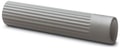
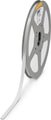
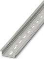 NS 35/ 7,5 PERF 2000MM - DIN rail perforated, Pack of 25 (50 m), acc. to EN 60715, material: Steel, galvanized, passivated with a thick layer, Standard profile, color: silver
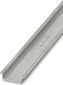 NS 35/ 7,5 UNPERF 2000MM - DIN rail, unperforated, Pack of 25 (50 m), acc. to EN 60715, material: Steel, galvanized, passivated with a thick layer, Standard profile, color: silver
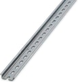 NS 35/ 7,5 WH PERF 2000MM - DIN rail perforated, Pack of 25 (50 m), acc. to EN 60715, material: Steel, Galvanized, white passivated, Standard profile, color: silver
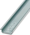 NS 35/ 7,5 WH UNPERF 2000MM-VPE 10 - DIN rail, unperforated, Pack of 10 (20 m), acc. to EN 60715, material: Steel, Galvanized, white passivated, Standard profile, color: silver
- NS 35/ 7,5 AL UNPERF 2000MM - DIN rail, unperforated, Pack of 25 (50 m), acc. to EN 60715, material: Aluminum, uncoated, Standard profile, color: silver
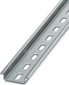 DIN rail perforated, Pack of 25 (50 m), acc. to EN 60715, material: Steel, galvanized, Standard profile, color: silver
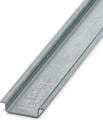 NS 35/ 7,5 ZN UNPERF 2000MM - DIN rail, unperforated, Pack of 25 (50 m), acc. to EN 60715, material: Steel, galvanized, Standard profile, color: silver
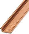 NS 35/ 7,5 CU UNPERF 2000MM-VPE 10 - DIN rail, unperforated, Pack of 10 (20 m), acc. to EN 60715, material: Copper, uncoated, Standard profile, color: copper-colored
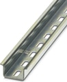 NS 35/15 PERF 2000MM - DIN rail perforated, Pack of 25 (50 m), similar to EN 60715, material: Steel, galvanized, passivated with a thick layer, Standard profile, color: silver
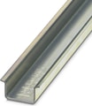 NS 35/15 UNPERF 2000MM - DIN rail, unperforated, Pack of 25 (50 m), similar to EN 60715, material: Steel, galvanized, passivated with a thick layer, Standard profile, color: silver
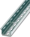 NS 35/15 WH PERF 2000MM - DIN rail perforated, Pack of 25 (50 m), similar to EN 60715, material: Steel, Galvanized, white passivated, Standard profile, color: white
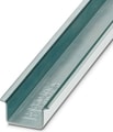 NS 35/15 WH UNPERF 2000MM-VPE 10 - DIN rail, unperforated, Pack of 10 (20 m), similar to EN 60715, material: Steel, Galvanized, white passivated, Standard profile, color: silver
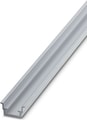 NS 35/15 AL UNPERF 2000MM - DIN rail, unperforated, similar to EN 60715, material: Aluminum, uncoated, Standard profile, color: silver
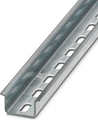 NS 35/15 ZN PERF 2000MM - DIN rail perforated, Pack of 25 (50 m), similar to EN 60715, material: Steel, galvanized, Standard profile, color: silver
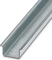 NS 35/15 ZN UNPERF 2000MM - DIN rail, unperforated, Pack of 25 (50 m), similar to EN 60715, material: Steel, galvanized, Standard profile, color: silver
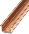 NS 35/15 CU UNPERF 2000MM-VPE 10 - DIN rail, unperforated, Pack of 10 (20 m), similar to EN 60715, material: Copper, uncoated, Standard profile, color: copper-colored
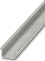 NS 35/15-2,3 UNPERF 2000MM-VPE 10 - DIN rail, unperforated, Pack of 10 (20 m), acc. to EN 60715, material: Steel, galvanized, passivated with a thick layer, Standard profile 2.3 mm, color: silver
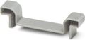
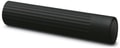
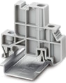 E/UK 1 - End clamps, for supporting the ends of double-level and three-level terminal blocks, width: 10 mm, color: gray
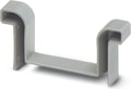
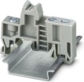
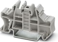 CLIPFIX 35 - Quick mounting end clamp for NS 35/7,5 DIN rail or NS 35/15 DIN rail, with marking option, width: 9.5 mm, color: gray
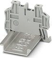 CLIPFIX 35-5 - Quick mounting end clamp for NS 35/7,5 DIN rail or NS 35/15 DIN rail, with marking option, with parking option for FBS...5, FBS...6, KSS 5, KSS 6, width: 5.15 mm, color: gray


Why Proax for Phoenix Contact 3211485?
Proax is an authorized distributor of Phoenix Contact 3211485 and one of Phoenix Contact's largest distributors in North America. Our highly skilled in-house technical team is ready to assist with any technical needs.
Have a question in mind? to help you get the right product as quickly as possible for your project. We're always here to help!
| Pack Size | 50 |
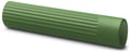
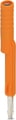
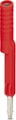
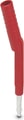
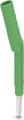
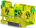 PT 6-TWIN-PE - Ground terminal, number of connections: 3, connection method: Push-in connection, cross section: 0.5 mm2 - 10 mm2, mounting type: NS 35/7,5, NS 35/15, color: green-yellow
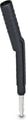
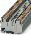 PT 6-TG - Disconnect terminal block, Current and voltage are determined by the plug used., nom. voltage: 500 V, nominal current: 20 A, connection method: Push-in connection, Rated cross section: 6 mm2, cross section: 0.5 mm2 - 10 mm2, mounting: NS 35/7,5, NS 35/15, color: gray
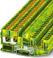 PT 6-QUATTRO/2P-PE - Ground terminal, number of connections: 4, connection method: Push-in / plug connection, cross section: 0.5 mm2 - 10 mm2, mounting type: NS 35/7,5, NS 35/15, color: green-yellow
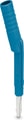
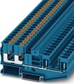 PT 6-QUATTRO/2P BU - Feed-through terminal block, nom. voltage: 1000 V, nominal current: 41 A, number of connections: 4, connection method: Push-in / plug connection, Rated cross section: 6 mm2, cross section: 0.5 mm2 - 10 mm2, mounting type: NS 35/7,5, NS 35/15, color: blue
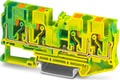 PT 6-QUATTRO-PE - Ground terminal, number of connections: 4, connection method: Push-in connection, cross section: 0.5 mm2 - 10 mm2, mounting type: NS 35/7,5, NS 35/15, color: green-yellow