1344361
SKU
PHX1344361
MPN
CAPAROC E2 12-24DC/1-4A EX
Series CAPAROC-E
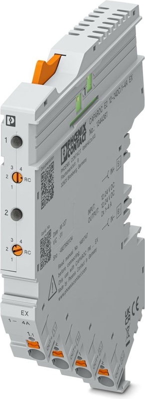
CAPAROC E2 12-24DC/1-4A EX - Electronic circuit breaker
2-channel electronic circuit breaker module for protecting 12 V DC and 24 V DC loads against overload and short circuit. Nominal current adjustable from 1 A to 4 A via step switch. EX e approval for zone 2. For DIN rail installation via the CAPAROC current rails.
- The customizable standard, thanks to individual combinations of the future-proof modular system
- Easy operation for everyone through tool-free assembly, uninterrupted installation, and transparent operating state
- Strikingly simple design-in with extensive support from the selection up to digital services
Technical Specifications
General
| Note | LABS release – in accordance with test specification VW PV 3.10.7:2005-0 |
| Note | When connecting the conductor, make sure that the CAPAROC modules are not pulled apart due to tensile force. Gaps must not be created between the modules. |
| Note | Observe the specified conditions for use in potentially explosive areas. Install the device in a suitable approved housing with at least IP54 degree of protection that meets the requirements of IEC/EN 60079-0. Also observe the requirements of IEC/EN 60079-14. |
Product properties
| Product family | CAPAROC |
| Number of Positions | 1 |
| No. of channels | 2 |
| Number of slots | 2 |
Insulation characteristics
| Protection class | III |
| Pollution degree | 2 |
General
| Operating Voltage | 10 V DC ... 30 V DC |
| Rated voltage | 12 V DC |
| Rated voltage | 24 V DC |
| Rated current IN | 4 A DC (per channel) |
| Rated current IN | 1 / 2 / 3 / 4 A DC (Adjustable via rotary coding switches) |
| Rated current IN | 1 / 2 / 3 / 4 A DC (can be set, in RC mode via power module with communication interface) |
| Rated current (pre-adjusted) | 1 A |
| Rated surge voltage | 0.5 kV |
| Tripping method | E (electronic) |
| Feedback resistance | max. 35 V DC |
| Switch-on delay | 50 ms (each channel preset by default) |
| Switch-on delay | can be adapted with CAPAROC PM IOL and CAPAROC PM PN power modules |
| Required backup fuse | Only required if Imax of the power supply > the short-circuit switching capacity. Integrated failsafe element. |
| Short-circuit switching capacity | 300 A |
| Dielectric strength | 35 V DC (Load circuit) |
| Active current limitation | typ. 2.0 x IN at IN ≤ 3 A |
| Active current limitation | typically 1.5 x IN at IN = 4 A |
| Fuse | electronic |
| Efficiency | > 99 % |
| Closed circuit current I0 | typ. 25 mA (no load at 24 V) |
| Power dissipation | typ. 0.6 W (no load at 24 V) |
| Power dissipation | < 1.1 W (in nominal operation at 24 V and 4 A) |
| Measuring tolerance I | ± 10 % (2 A ... 4 A) |
| Measuring tolerance I | ± 20 % (1 A) |
| MTBF (IEC 61709, SN 29500) | 11364927 h (at 25 °C with 21 % load) |
| MTBF (IEC 61709, SN 29500) | 5271554 h (at 40°C with 34.25% load) |
| MTBF (IEC 61709, SN 29500) | 640731 h (at 65°C with 100% load) |
| Voltage drop | 0.06 V (at 4 A) |
| Fail-safe element | 5 A DC (per output channel) |
Load circuit
| Shutdown time | 5 s (with overload 1.1…1.3 x IN at IN ≥ 4 A) |
| Shutdown time | 5 s (for overload 1.1…1.7 x IN at IN < 4 A) |
| Shutdown time | ≤ 400 ms (max. 450 ms for high starting currents) |
| Shutdown time | typ. 20 ms (for short circuit > 1,5 x IN) |
| Undervoltage switch-off | ≤ 8.5 V DC (active) |
| Undervoltage switch-off | ≥ 9.2 V DC (inactive) |
| Overvoltage switch-off | ≥ 32.5 V DC (active) |
| Overvoltage switch-off | ≤ 30.5 V DC (inactive) |
| Max. capacitive load | ≤ 60000 µF (Depending on the current setting and the short-circuit current available) |
Fuse-protected output
| Connection Method | Push-in connection |
| Stripping length | 10 mm |
| Conductor cross section flexible | 0.2 mm² ... 4 mm² |
| Conductor cross section rigid | 0.2 mm² ... 4 mm² |
| Conductor cross section AWG | 24 ... 12 |
| Conductor cross section, flexible, with ferrule, with plastic sleeve | 0.25 mm² ... 4 mm² |
| Conductor cross section flexible, with ferrule without plastic sleeve | 0.25 mm² ... 4 mm² |
Signaling
| Channel LED off | off (Channel switched off) |
| Channel LED yellow | lit (Channel switched on, channel load > 80% ) |
| Channel LED yellow | two flashes (Check the installation, no communication to power module) |
| Channel LED green | lit (Channel switched on) |
| Channel LED green | flashing (Channel switched on, coding switch position is not equal to set value) |
| Channel LED red | lit (Channel switched off, over- or undervoltage active) |
| Channel LED red | ON temporarily (Channel switched off, 5 s cool-down phase, overload or short-circuit release) |
| Channel LED red | flashing (Channel switched off, ready to be switched back on, overload or short-circuit release) |
| Channel LED red | two flashes (Channel switched off, system total current limit exceeded) |
| Channel LED red-yellow | flashing (Channel is overloaded and is switched off) |
| Channel LED red-green | flashing (Channel switched off, programming mode active, current adjustment after overload or short-circuit release) |
Dimensions
| Width | 12.4 mm |
| Height | 132.4 mm |
| Depth | 111.3 mm (incl. DIN rail 7.5 mm) |
Material specifications
| Color | light grey (RAL 7035) |
| Material | PA 6 |
| Material | PA 6 |
| Material | PA 6 |
| Material | PC |
| Flammability rating according to UL 94 | V-0 |
Ambient conditions
| Degree of Protection | IP20 |
| Ambient Temperature (Operation) | -30 °C ... 65 °C (The temperature range of the power module must be taken into consideration) |
| Ambient temperature (storage/transport) | -40 °C ... 70 °C |
| Altitude | ≤ 4000 m (amsl) |
| Humidity test | 96 h, 95 % RH, 40 °C |
| Shock (operation) | 30g (11 ms period, half-sine shock pulse, according to IEC 60068-2-27) |
| Shock (operation) | 25g (6 ms duration, half-sine shock pulse in accordance with IEC 60068-2-27, continuous shock) |
| Vibration (Operation) | 5g (10 ... 150 Hz / 10 cycles / axis / X, Y, Z) |
UL approval
| Identification | UL/C-UL Listed UL 508 |
| Identification | UL Recognized UL 2367 |
| Identification | UL 121201 Class I, Division 2, Groups A, B, C, D, T4A |
| Identification | NEC Class 2 according to UL 1310 |
ATEX
| Identification | TÜV 22 ATEX 8874 X |
| Identification | II 3G Ex ec IIC T4 Gc |
IECEx
| Identification | IECEx TUR 22.0049X |
| Identification | II 3G Ex ec IIC T4 Gc |
UKCA Ex (UKEX)
| Identification | TÜV 22 UKEX 7109 X |
| Identification | II 3G Ex ec IIC T4 Gc |
Corrosive gas test
| Identification | ISA S71.04.2013 G3 Harsh Group A |
Standards and Regulations
| Standards/specifications | EN 61000-6-2 |
| Note | EMC – Immunity for industrial areas |
| Standards/specifications | EN 61000-6-3 |
| Note | EMC – Emission for residential, business and commercial properties and small operations |
| Standards/specifications | EN 60068-2-78 |
| Note | Environmental influences – Moisture and heat, constant |
| Standards/specifications | EN 50178 |
| Note | Equipping power installations with electronic equipment |
| Standards/specifications | EN 60068-2-6 |
| Note | Environmental influences – Vibrations (sinusoidal) |
| Standards/specifications | EN 60068-2-27 |
| Note | Environmental influences – Shocks |
| Standards/specifications | IEC 60079-7 |
| Note | Explosive atmospheres – Part 7: Equipment protection by increased safety “e” |
| Standards/specifications | IEC 60079-0 |
| Note | Explosive atmospheres – Part 0: Equipment – General requirements |
Mounting
| Mounting Type | pluggable onto CAPAROC CR… current rail |
Why Proax for Phoenix Contact 1344361?
Proax is an authorized distributor of Phoenix Contact 1344361 and one of Phoenix Contact's largest distributors in North America. Our highly skilled in-house technical team is ready to assist with any technical needs.
Have a question in mind? to help you get the right product as quickly as possible for your project. We're always here to help!
Short Lead Time
Highly Trained Staff
Live Chat
Technical Support
Local Inventory
60+ Years Experience
Additional Information
| Pack Size | 1 |
Recommended

 CAPAROC E2 12-24DC/1-4A - 2-channel electronic circuit breaker module for protecting 12 and 24 V DC loads against overload and short circuit. Nominal current adjustable from 1 A to 4 A via step switch. For DIN rail installation via the CAPAROC current rails.
 CAPAROC E2 12-24DC/2-10A - 2-channel electronic circuit breaker module for protecting 12 and 24 V DC loads against overload and short circuit. Nominal current adjustable from 2 A to 10 A via step switch. For DIN rail installation via the CAPAROC current rails.
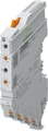 CAPAROC E2 12-24DC/2-10A EX - 2-channel electronic circuit breaker module for protecting 12 V DC and 24 V DC loads against overload and short circuit. Nominal current adjustable from 2 A to 10 A via step switch. EX e approval for zone 2. For DIN rail installation via the CAPAROC current rails.
 CAPAROC E1 12-24DC/1-10A - 1-channel electronic circuit breaker module for protecting 12 and 24 V DC loads against overload and short circuit. Nominal current adjustable from 1 A to 10 A via LED button. For DIN rail installation via the CAPAROC current rails.
 CAPAROC E1 12-24DC/10A - 1-channel electronic circuit breaker module for protecting 12 and 24 V DC loads against overload and short circuit. With fixed nominal current. For DIN rail installation via the CAPAROC current rails.
 CAPAROC E1 12-24DC/1A - 1-channel electronic circuit breaker module for protecting 12 and 24 V DC loads against overload and short circuit. With fixed nominal current. For DIN rail installation via the CAPAROC current rails.
 CAPAROC E1 12-24DC/2A - 1-channel electronic circuit breaker module for protecting 12 and 24 V DC loads against overload and short circuit. With fixed nominal current. For DIN rail installation via the CAPAROC current rails.
 CAPAROC E1 12-24DC/4A - 1-channel electronic circuit breaker module for protecting 12 and 24 V DC loads against overload and short circuit. With fixed nominal current. For DIN rail installation via the CAPAROC current rails.
 CAPAROC E1 12-24DC/6A - 1-channel electronic circuit breaker module for protecting 12 and 24 V DC loads against overload and short circuit. With fixed nominal current. For DIN rail installation via the CAPAROC current rails.
 CAPAROC E1 12-24DC/8A - 1-channel electronic circuit breaker module for protecting 12 and 24 V DC loads against overload and short circuit. With fixed nominal current. For DIN rail installation via the CAPAROC current rails.
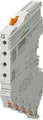 CAPAROC E4 12-24DC/1-10A - Four-channel electronic circuit breaker module for protecting 12 and 24 V DC loads against overload and short circuit. Nominal current adjustable from 1 A to 10 A via LED button. For DIN rail installation via the CAPAROC current rails.
 CAPAROC E4 12-24DC/1-4A - Four-channel electronic circuit breaker module for protecting 12 and 24 V DC loads against overload and short circuit. Nominal current adjustable from 1 A to 4 A via LED button. For DIN rail installation via the CAPAROC current rails.
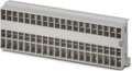
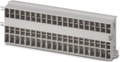 CAPAROC CR EXT20 - Extension busbar with 20 slots for the CAPAROC system. For installation on a DIN rail.
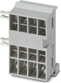 CAPAROC CR EXT4 - Extension busbar with 4 slots for the CAPAROC system. For installation on a DIN rail.
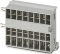 CAPAROC CR EXT8 - Extension busbar with 8 slots for CAPAROC system. For installation on a DIN rail.
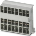
 CAPAROC PD 0V - Potential distributor with Push-in connections for directly connecting the 0 V return conductor in the CAPAROC system. For DIN rail installation via the CAPAROC current rails.
 Power module with IO-Link interface for supplying the CAPAROC circuit breaker system with 12 or 24 V DC for up to 20 channels. For DIN rail installation via the CAPAROC current rails.