


SKU
MPN
PTFIX 18X4-NS35 BU
Weight
0.047 kg
This product is Not Cancellable/Not Returnable
Series PTFIX
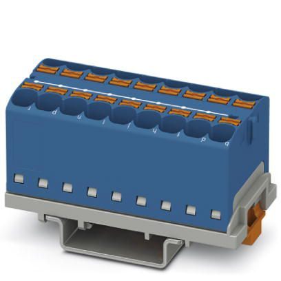
PTFIX 18X4-NS35 BU - Distribution block
Distribution block, Block with vertical alignment, nom. voltage: 800 V, nominal current: 32 A, number of connections: 18, connection method: Push-in connection, cross section: 0.2 mm2 - 6 mm2, mounting type: NS 35/7,5, NS 35/15, color: blue
- Space savings of up to 50 % on the DIN rail, thanks to transverse mounting
- Flexible use, thanks to DIN rail mounting, direct mounting or adhesive mounting
- Clear wiring, thanks to eleven different color variants
- Time savings of up to 80 %, thanks to ready-to-mount blocks without manual bridging
- Time-saving conductor connection, thanks to tool-free Push-in direct connection technology
Documents
PTFIX
The Phoenix Contact PTFIX Series comprises ready-to-use distribution blocks featuring Push-in connection technology, designed to streamline potential distribution in control cabinets and various industrial applications. These blocks facilitate quick, tool-free wiring, enhancing installation efficiency and flexibility.
Key Features:
Ready-to-Connect Design: PTFIX blocks are pre-assembled and maintenance-free, allowing for immediate deployment without the need for manual bridging.
Push-in Connection Technology: This tool-free, direct plug-in method enables the easy insertion of solid and flexible conductors with ferrules, starting from 0.25 mm², reducing installation time.
Compact and Space-Saving: The compact design of PTFIX blocks saves space in control cabinets, making them ideal for applications with limited installation areas.
Versatile Mounting Options: Various adapters allow for DIN rail, direct, and adhesive mounting, providing flexibility to suit different installation requirements.
Color-Coded Variants: Available in up to 11 different colors, PTFIX blocks support intuitive and safe installation by enabling clear potential assignment.
Technical Specifications
Notes
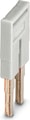
| Notes on operation | the blocks can be bridged with one another via the conductor shaft, for corresponding plug-in bridges, see accessories |
General
| Note | The maximum load current of a single clamping unit must not be exceeded. |
Product properties
| Number of Connections | 18 |
| Number of rows | 1 |
| Potentials | 1 |
Insulation characteristics
| Overvoltage category | III |
| Degree of pollution | 3 |
Electrical properties
| Rated surge voltage | 6 kV |
| Maximum power dissipation for nominal condition | 1.02 W |
Connection data
| Number of connections per level | 18 |
| Nominal cross section | 4 mm² |
| Rated cross section AWG | 10 |
| Stripping length | 10 mm ... 12 mm |
| Internal cylindrical gage | A4 |
| Connection in acc. with standard | IEC 60947-7-1 |
| Conductor cross section rigid | 0.2 mm² ... 6 mm² |
| Cross section AWG | 24 ... 10 (converted acc. to IEC) |
| Conductor cross section flexible | 0.2 mm² ... 6 mm² |
| Conductor cross section, flexible [AWG] | 24 ... 10 (converted acc. to IEC) |
| Conductor cross-section flexible (ferrule without plastic sleeve) | 0.2 mm² ... 4 mm² |
| Flexible conductor cross section (ferrule with plastic sleeve) | 0.2 mm² ... 4 mm² |
| 2 conductors with the same cross section, flexible, with TWIN ferrule with plastic sleeve | 0.5 mm² ... 1 mm² |
| Nominal Current | 32 A |
| Maximum Load Current | 41 A |
| Maximum total current | 63 A |
| Nominal Voltage | 800 V |
Connection cross sections directly pluggable
| Conductor cross section rigid | 0.5 mm² ... 6 mm² |
| Conductor cross section, rigid [AWG] | 20 ... 10 (converted acc. to IEC) |
| Conductor cross-section flexible (ferrule without plastic sleeve) | 0.75 mm² ... 4 mm² |
| Flexible conductor cross section (ferrule with plastic sleeve) | 0.5 mm² ... 4 mm² |
Dimensions
| Width | 28.6 mm |
| Height | 58.1 mm |
| Depth on NS 15 | 30.4 mm |
| Depth on NS 35/7,5 | 32.4 mm |
Material specifications
| Color | blue (RAL 5015) |
| Flammability rating according to UL 94 | V0 |
| Insulating material group | I |
| Insulating material | PA |
| Static insulating material application in cold | -60 °C |
| Temperature index of insulation material (DIN EN 60216-1 (VDE 0304-21)) | 130 °C |
| Relative insulation material temperature index (Elec., UL 746 B) | 130 °C |
| Fire protection for rail vehicles (DIN EN 45545-2) R22 | HL 1 - HL 3 |
| Fire protection for rail vehicles (DIN EN 45545-2) R23 | HL 1 - HL 3 |
| Fire protection for rail vehicles (DIN EN 45545-2) R24 | HL 1 - HL 3 |
| Fire protection for rail vehicles (DIN EN 45545-2) R26 | HL 1 - HL 3 |
| Calorimetric heat release NFPA 130 (ASTM E 1354) | 28 MJ/kg |
| Surface flammability NFPA 130 (ASTM E 162) | passed |
| Specific optical density of smoke NFPA 130 (ASTM E 662) | passed |
| Smoke gas toxicity NFPA 130 (SMP 800C) | passed |
Surge voltage test
| Test voltage setpoint | 9.8 kV |
| Result | Test passed |
Temperature-rise test
| Requirement temperature-rise test | Increase in temperature ≤ 45 K |
| Result | Test passed |
| Short-time withstand current 4 mm² | 0.48 kA |
| Short-time withstand current 6 mm² | 0.72 kA |
| Result | Test passed |
Power-frequency withstand voltage
| Test voltage setpoint | 2 kV |
| Result | Test passed |
Mechanical data
| Open side panel | No |
Mechanical strength
| Result | Test passed |
Attachment on the carrier
| DIN rail/fixing support | NS 35/NS 15 |
| Test force setpoint | 5 N |
| Result | Test passed |
| Note | When aligning several blocks, it is recommended to either place a DIN rail adapter underneath the connection point or a flange element between the blocks. |
| Note | For versions with 6 or 7 connections, it is enough to place one DIN rail adapter centrally per block and place flange elements after every other block. |
| Note | When using the DIN rail adapter PTFIX-NS35, an aligned block must not protrude by more than a half. |
Test for conductor damage and slackening
| Rotation speed | 10 rpm |
| Revolutions | 135 |
| Conductor cross section/weight | 0.2 mm² / 0.2 kg |
| Conductor cross section/weight | 4 mm² / 0.9 kg |
| Conductor cross section/weight | 6 mm² / 1.4 kg |
| Result | Test passed |
Aging
| Temperature cycles | 192 |
| Result | Test passed |
Needle-flame test
| Time of exposure | 30 s |
| Result | Test passed |
Oscillation/broadband noise
| Specification | DIN EN 50155 (VDE 0115-200):2008-03 |
| Spectrum | Service life test category 2, bogie-mounted |
| Frequency | f1 = 5 Hz to f2 = 250 Hz |
| ASD level | 6.12 (m/s²)²/Hz |
| Acceleration | 3.12g |
| Test duration per axis | 5 h |
| Test directions | X-, Y- and Z-axis |
| Result | Test passed |
Shocks
| Specification | DIN EN 50155 (VDE 0115-200):2008-03 |
| Pulse shape | Half-sine |
| Acceleration | 30g |
| Shock duration | 18 ms |
| Number of shocks per direction | 3 |
| Test directions | X-, Y- and Z-axis (pos. and neg.) |
| Result | Test passed |
Ambient conditions
| Ambient Temperature (Operation) | -60 °C ... 110 °C (Operating temperature range incl. self-heating; for max. short-term operating temperature, see RTI Elec.) |
| Ambient temperature (storage/transport) | -25 °C ... 60 °C (for a short time, not exceeding 24 h, -60 °C to +70 °C) |
| Ambient temperature (assembly) | -5 °C ... 70 °C |
| Ambient temperature (actuation) | -5 °C ... 70 °C |
| Permissible humidity (operation) | 20 % ... 90 % |
| Permissible humidity (storage/transport) | 30 % ... 70 % |
Standards and Regulations
| Connection in acc. with standard | IEC 60947-7-1 |
Mounting
| Mounting Type | NS 35/7,5 |
| Mounting Type | NS 35/15 |
Accessories


Why Proax for Phoenix Contact 3273572?
Proax is an authorized distributor of Phoenix Contact 3273572 and one of Phoenix Contact's largest distributors in North America. Our highly skilled in-house technical team is ready to assist with any technical needs.
Have a question in mind? to help you get the right product as quickly as possible for your project. We're always here to help!
Short Lead Time
Highly Trained Staff
Live Chat
Technical Support
Local Inventory
60+ Years Experience
Additional Information
| Pack Size | 8 |
Recommended

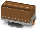 PTFIX 18X4-NS35 BN - Distribution block, Block with vertical alignment, nom. voltage: 800 V, nominal current: 32 A, number of connections: 18, connection method: Push-in connection, cross section: 0.2 mm2 - 6 mm2, mounting type: NS 35/7,5, NS 35/15, color: brown
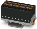 PTFIX 18X4-NS35 BK - Distribution block, Block with vertical alignment, nom. voltage: 800 V, nominal current: 32 A, number of connections: 18, connection method: Push-in connection, cross section: 0.2 mm2 - 6 mm2, mounting type: NS 35/7,5, NS 35/15, color: black
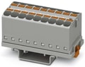 PTFIX 18X4-NS35 GY - Distribution block, Block with vertical alignment, nom. voltage: 800 V, nominal current: 32 A, number of connections: 18, connection method: Push-in connection, cross section: 0.2 mm2 - 6 mm2, mounting type: NS 35/7,5, NS 35/15, color: gray
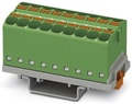 Distribution block, Block with vertical alignment, nom. voltage: 800 V, nominal current: 32 A, number of connections: 18, connection method: Push-in connection, cross section: 0.2 mm2 - 6 mm2, mounting type: NS 35/7,5, NS 35/15, color: green
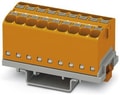 PTFIX 18X4-NS35 OG - Distribution block, Block with vertical alignment, nom. voltage: 800 V, nominal current: 32 A, number of connections: 18, connection method: Push-in connection, cross section: 0.2 mm2 - 6 mm2, mounting type: NS 35/7,5, NS 35/15, color: orange
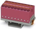 PTFIX 18X4-NS35 PK - Distribution block, Block with vertical alignment, nom. voltage: 800 V, nominal current: 32 A, number of connections: 18, connection method: Push-in connection, cross section: 0.2 mm2 - 6 mm2, mounting type: NS 35/7,5, NS 35/15, color: pink
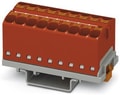 PTFIX 18X4-NS35 RD - Distribution block, Block with vertical alignment, nom. voltage: 800 V, nominal current: 32 A, number of connections: 18, connection method: Push-in connection, cross section: 0.2 mm2 - 6 mm2, mounting type: NS 35/7,5, NS 35/15, color: red
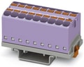 PTFIX 18X4-NS35 VT - Distribution block, Block with vertical alignment, nom. voltage: 800 V, nominal current: 32 A, number of connections: 18, connection method: Push-in connection, cross section: 0.2 mm2 - 6 mm2, mounting type: NS 35/7,5, NS 35/15, color: violet
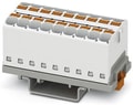 PTFIX 18X4-NS35 WH - Distribution block, Block with vertical alignment, nom. voltage: 800 V, nominal current: 32 A, number of connections: 18, connection method: Push-in connection, cross section: 0.2 mm2 - 6 mm2, mounting type: NS 35/7,5, NS 35/15, color: white
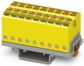 PTFIX 18X4-NS35 YE - Distribution block, Block with vertical alignment, nom. voltage: 800 V, nominal current: 32 A, number of connections: 18, connection method: Push-in connection, cross section: 0.2 mm2 - 6 mm2, mounting type: NS 35/7,5, NS 35/15, color: yellow
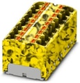 PTFIX 18X4-NS35-FE - Distribution block, Block with vertical alignment, nom. voltage: 800 V, nominal current: 32 A, number of connections: 18, connection method: Push-in connection, cross section: 0.2 mm2 - 6 mm2, mounting type: NS 35/7,5, NS 35/15, color: black/yellow
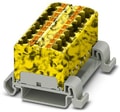 PTFIX 18X4-NS35A-FE - Distribution block, Block with horizontal alignment, nom. voltage: 800 V, nominal current: 32 A, number of connections: 18, connection method: Push-in connection, cross section: 0.2 mm2 - 6 mm2, mounting type: NS 35/7,5, NS 35/15, color: black/yellow
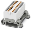 PTFIX 18X4-NS35A WH - Distribution block, Block with horizontal alignment, nom. voltage: 800 V, nominal current: 32 A, number of connections: 18, connection method: Push-in connection, cross section: 0.2 mm2 - 6 mm2, mounting type: NS 35/7,5, NS 35/15, color: white
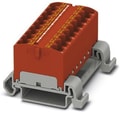 PTFIX 18X4-NS35A RD - Distribution block, Block with horizontal alignment, nom. voltage: 800 V, nominal current: 32 A, number of connections: 18, connection method: Push-in connection, cross section: 0.2 mm2 - 6 mm2, mounting type: NS 35/7,5, NS 35/15, color: red
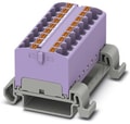 PTFIX 18X4-NS35A VT - Distribution block, Block with horizontal alignment, nom. voltage: 800 V, nominal current: 32 A, number of connections: 18, connection method: Push-in connection, cross section: 0.2 mm2 - 6 mm2, mounting type: NS 35/7,5, NS 35/15, color: violet
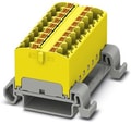 PTFIX 18X4-NS35A YE - Distribution block, Block with horizontal alignment, nom. voltage: 800 V, nominal current: 32 A, number of connections: 18, connection method: Push-in connection, cross section: 0.2 mm2 - 6 mm2, mounting type: NS 35/7,5, NS 35/15, color: yellow
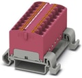 PTFIX 18X4-NS35A PK - Distribution block, Block with horizontal alignment, nom. voltage: 800 V, nominal current: 32 A, number of connections: 18, connection method: Push-in connection, cross section: 0.2 mm2 - 6 mm2, mounting type: NS 35/7,5, NS 35/15, color: pink
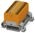 PTFIX 18X4-NS35A OG - Distribution block, Block with horizontal alignment, nom. voltage: 800 V, nominal current: 32 A, number of connections: 18, connection method: Push-in connection, cross section: 0.2 mm2 - 6 mm2, mounting type: NS 35/7,5, NS 35/15, color: orange
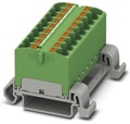 PTFIX 18X4-NS35A GN - Distribution block, Block with horizontal alignment, nom. voltage: 800 V, nominal current: 32 A, number of connections: 18, connection method: Push-in connection, cross section: 0.2 mm2 - 6 mm2, mounting type: NS 35/7,5, NS 35/15, color: green
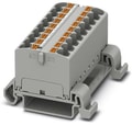 PTFIX 18X4-NS35A GY - Distribution block, Block with horizontal alignment, nom. voltage: 800 V, nominal current: 32 A, number of connections: 18, connection method: Push-in connection, cross section: 0.2 mm2 - 6 mm2, mounting type: NS 35/7,5, NS 35/15, color: gray