2320898
SKU
PHX2320898
MPN
QUINT-PS/1AC/24DC/20/CO
Weight
2.164 kg
Series QUINT-PS
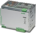
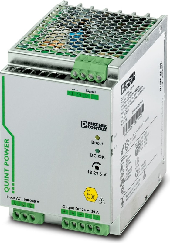
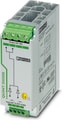
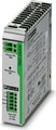
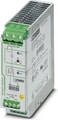
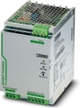
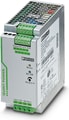
QUINT-PS/1AC/24DC/20/CO - Power supply, with protective coating
Primary-switched power supply unit QUINT POWER, Screw connection, DIN rail mounting, SFB Technology (Selective Fuse Breaking), input: 1-phase, output: 24 V DC / 20 A
- For superior system availability
- Reliable starting of difficult loads with the static POWER BOOST power reserve with up to 1.5 times the nominal current permanently
- Fast tripping of standard circuit breakers with dynamic power reserve SFB (selective fuse breaking) technology with up to 6 times the nominal current for 12 ms
- Preventive function monitoring
- Optimum protection with dip coating for 100 % humidity
QUINT-PS
The Phoenix Contact QUINT-PS Series is a line of high-performance power supplies designed to ensure maximum system availability in demanding industrial applications. These power supplies are equipped with advanced features such as Selective Fuse Breaking (SFB) Technology, preventive function monitoring, and configurable settings to meet diverse operational requirements.
Key Features:
SFB Technology: The QUINT-PS Series utilizes SFB Technology to deliver up to six times the nominal current for 12 milliseconds, enabling standard circuit breakers to trip selectively. This ensures that only the faulty circuit is disconnected, while critical system components continue to operate without interruption.
Preventive Function Monitoring: These power supplies continuously monitor critical operating parameters and provide early warning signals before faults occur. This proactive approach allows for timely maintenance and reduces the risk of unexpected system downtime.
Power Boost: The QUINT-PS Series offers a static power reserve, known as POWER BOOST, providing up to 125% of the nominal power continuously. This feature facilitates the reliable startup of heavy loads and simplifies system expansion without the need for additional power supplies.
Configurable Settings: Users can customize signaling thresholds and characteristic curves to match specific application needs, enhancing flexibility and adaptability in various industrial environments.
Technical Specifications
AC operation
| Nominal input voltage range | 100 V AC ... 240 V AC |
| Nominal input voltage range | 110 V DC ... 250 V DC |
| Input voltage range | 85 V AC ... 264 V AC |
| Input voltage range | 90 V DC ... 410 V DC +5 % (UL 508: ≤ 250 V DC) |
| Input Voltage Range AC | 85 V AC ... 264 V AC |
| Input voltage range DC | 90 V DC ... 410 V DC +5 % (UL 508: ≤ 250 V DC) |
| Electric strength, max. | 300 V AC |
| Voltage type of supply voltage | AC/DC |
| Inrush Current | < 20 A |
| Inrush current integral (I2t) | < 3.2 A2s |
| AC frequency range | 45 Hz ... 65 Hz |
| Frequency range DC | 0 Hz |
| Mains buffering time | typ. 32 ms (120 V AC) |
| Mains buffering time | typ. 32 ms (230 V AC) |
| Current consumption | 7 A (100 V AC) |
| Current consumption | 3.1 A (240 V AC) |
| Current consumption | 5.1 A (120 V AC) |
| Current consumption | 2.3 A (230 V AC) |
| Current consumption | 4.9 A (110 V DC) |
| Current consumption | 2.4 A (220 V DC) |
| Current consumption | 6.3 A (110 V DC) |
| Current consumption | 2.7 A (250 V DC) |
| Nominal Power Consumption | 569 VA |
| Protective circuit | Transient surge protection; Varistor, gas-filled surge arrester |
| Typical response time | < 0.6 s |
| Input fuse | 12 A (slow-blow, internal) |
| Permissible backup fuse | B10 B16 AC: |
| Permissible DC backup fuse | DC: Connect a suitable fuse upstream |
| Recommended breaker for input protection | 10 A ... 16 A (AC: Characteristics B, C, D, K) |
| Discharge current to PE | < 3.5 mA |
Output data
| Efficiency | > 93 % (230 V AC) |
| Nominal Output Voltage | 24 V DC ±1 % |
| Setting range of the output voltage (USet) | 18 V DC ... 29.5 V DC (> 24 V DC, constant capacity restricted) |
| Nominal output current (IN) | 20 A (-25 °C ... 60 °C, UOUT = 24 V DC) |
| POWER BOOST (IBoost) | 26 A (-25 °C ... 40 °C permanent, UOUT = 24 V DC ) |
| Selective Fuse Breaking (ISFB) | 120 A (12 ms) |
| Magnetic circuit breaker tripping | B2 / B4 / B6 / B10 / B16 / C2 / C4 / C6 |
| Derating | 60 °C ... 70 °C (2.5 %/K) |
| Feedback voltage resistance | ≤ 35 V DC |
| Protection against overvoltage at the output (OVP) | < 32 V DC |
| Control deviation | < 1 % (change in load, static 10 % ... 90 %) |
| Control deviation | < 2 % (change in load, dynamic 10 % ... 90 %) |
| Control deviation | < 0.1 % (change in input voltage ±10 %) |
| Residual ripple | < 30 mVPP (with nominal values) |
| Output Power | 480 W |
| Maximum no-load power dissipation | 8 W |
| Power loss nominal load max. | 40 W |
| Rise time | < 0.1 s (UOUT (10 % ... 90 %)) |
| Connection in parallel | yes, for redundancy and increased capacity |
| Connection in series | yes |
Signal: DC OK active
| Output description | UOUT > 0.9 x UN: High signal |
| Switching voltage range | 18 V DC ... 24 V DC |
| Maximum Inrush Current | 20 mA (short-circuit-proof) |
| Continuous load current | ≤ 20 mA |
Signal: DC OK floating
| Output description | Relay contact, UOUT > 0.9 x UN: Contact closed |
| Maximum Switching Voltage | 30 V AC |
| Maximum Switching Voltage | 24 V DC |
| Maximum Inrush Current | 0.5 A |
| Maximum Inrush Current | 1 A |
| Continuous load current | ≤ 1 A |
Signal: POWER BOOST, active
| Output description | IOUT < IN: High signal |
| Switching voltage range | 18 V DC ... 24 V DC |
| Output Voltage | + 24 V DC |
| Maximum Inrush Current | 20 mA (short-circuit-proof) |
| Continuous load current | ≤ 20 mA |
Input
| Connection Method | Screw connection |
| Conductor cross section, rigid min. | 0.2 mm² |
| Conductor cross section, rigid max. | 6 mm² |
| Conductor cross section flexible min. | 0.2 mm² |
| Conductor cross section flexible max. | 4 mm² |
| Conductor cross section AWG min. | 18 |
| Conductor cross section AWG max. | 10 |
| Stripping length | 7 mm |
| Screw thread | M4 |
| Tightening torque, min | 0.5 Nm |
| Tightening torque max | 0.6 Nm |
Output
| Connection Method | Screw connection |
| Conductor cross section, rigid min. | 0.2 mm² |
| Conductor cross section, rigid max. | 6 mm² |
| Conductor cross section flexible min. | 0.2 mm² |
| Conductor cross section flexible max. | 4 mm² |
| Conductor cross section AWG min. | 12 |
| Conductor cross section AWG max. | 10 |
| Stripping length | 7 mm |
| Screw thread | M4 |
| Tightening torque, min | 0.5 Nm |
| Tightening torque max | 0.6 Nm |
Signal
| Conductor cross section, rigid min. | 0.2 mm² |
| Conductor cross section, rigid max. | 6 mm² |
| Conductor cross section flexible min. | 0.2 mm² |
| Conductor cross section flexible max. | 4 mm² |
| Conductor cross section AWG min. | 18 |
| Conductor cross section AWG max. | 10 |
| Screw thread | M4 |
| Tightening torque, min | 0.5 Nm |
| Tightening torque max | 0.6 Nm |
Signaling
| Types of signaling | LED |
| Types of signaling | Active switching output |
| Types of signaling | Relay contact |
Signal output: DC OK active
| Status display | UOUT > 0.9 x UN: "DC OK" LED green |
| Note on status display | UOUT < 0.9 x UN: Flashing "DC OK" LED |
| Note on status display | IOUT < IN: LED ON |
| Color | green |
| Note on status display | LED flashing |
Signal output: DC OK floating
| Status display | UOUT > 0.9 x UN: "DC OK" LED green |
| Note on status display | UOUT < 0.9 x UN: Flashing "DC OK" LED |
| Color | green |
| Note on status display | LED flashing |
Signal output: POWER BOOST, active
| Status display | IOUT > IN: LED "BOOST" yellow |
| Color | yellow |
Electrical properties
| Number of phases | 1.00 |
| Insulation voltage input/output | 4 kV AC (type test) |
| Insulation voltage input/output | 2 kV AC (routine test) |
| Insulation voltage output / PE | 500 V DC (routine test) |
| Insulation voltage input / PE | 3.5 kV AC (type test) |
| Insulation voltage input / PE | 2 kV AC (routine test) |
Product properties
| Product family | QUINT POWER |
| MTBF (IEC 61709, SN 29500) | > 900000 h (25 °C) |
| MTBF (IEC 61709, SN 29500) | > 520000 h (40 °C) |
Insulation characteristics
| Protection class | I |
| Degree of pollution | 2 |
Dimensions
| Width | 90 mm |
| Height | 130 mm |
| Depth | 125 mm |
Installation dimensions
| Installation distance right/left | 5 mm / 5 mm |
| Installation distance top/bottom | 50 mm / 50 mm |
Alternative assembly
| Width | 122 mm |
| Height | 130 mm |
| Depth | 93 mm |
Mounting
| Mounting Type | DIN rail mounting |
| Assembly instructions | alignable: PN ≥50%, 5 mm horizontally, 15 mm next to active components, 50 mm verticallyalignable: PN <50%, 0 mm horizontally, 40 mm vertically top, 20 mm vertically bottom |
| Mounting Position | horizontal DIN rail NS 35, EN 60715 |
| With protective coating | yes |
Material specifications
| Housing Material | Metal |
| Hood version | Galvanized sheet steel, free from chrome (VI) |
| Side element version | Aluminum |
Ambient conditions
| Degree of Protection | IP20 |
| Ambient Temperature (Operation) | -40 °C ... 70 °C (> 60 °C Derating: 2,5 %/K) |
| Ambient temperature (storage/transport) | -40 °C ... 85 °C |
| Maximum altitude | 6000 m |
| Climatic class | 3K3 (in acc. with EN 60721) |
| Max. permissible relative humidity (operation) | 100 % (at 25 °C, non-condensing) |
| Shock | 18 ms, 30g, in each space direction (according to IEC 60068-2-27) |
| Vibration (Operation) | < 15 Hz, amplitude ±2.5 mm (according to IEC 60068-2-6) |
| Vibration (Operation) | 15 Hz ... 150 Hz, 2.3g, 90 min. |
Standards and Regulations
| Rail applications | EN 50121-4 |
| Rail applications | EN 50121-3-2 |
| HART FSK Physical Layer Test Specification Compliance | Output voltage UOut compliant |
| Standard – Limitation of mains harmonic currents | EN 61000-3-2 |
| Standard - Electrical safety | IEC 61010-2-201 (SELV) |
| Explosive atmosphere | EN 60079-15 (Zone 2) |
| Standard - Equipment safety | BG (design tested) |
| Standard – Safety extra-low voltage | IEC 61010-1 (SELV) |
| Standard – Safety extra-low voltage | IEC 61010-2-201 (PELV) |
| Standard - Safe isolation | IEC 61010-2-201 |
| Standard - safety for equipment for measurement, control, and laboratory use | IEC 61010-1 |
| Noxious gas test | ISA-S71.04-1985 G3 Harsh Group A |
| Approval - requirement of the semiconductor industry with regard to mains voltage dips | SEMI F47-0706 Compliance Certificate |
| DeviceNet approval | DeviceNet™ Power Supply Conformance Tested |
Overvoltage category
| EN 62477-1 | III |
Approvals
| CSA | CAN/CSA-C22.2 No. 60950-1-07 |
| CSA | CSA-C22.2 No. 107.1-01 |
| Shipbuilding approval | DNV GL (EMC B, only with upstream filter) |
| SIQ | BG (type approved) |
| UL approvals | UL/C-UL listed UL 508 |
| UL approvals | UL/C-UL Recognized UL 60950-1 |
| UL approvals | UL ANSI/ISA-12.12.01 Class I, Division 2, Groups A, B, C, D (Hazardous Location) |
| DeviceNet approval | DeviceNet™ Power Supply Conformance Tested |
Conformity/Approvals
| ATEX | II 3 G Ex ec ic nC IIC T4 Gc |
| ATEX | SIQ 14 ATEX 137 X |
| IECEx | Ex ec ic nC IIC T4 Gc |
| IECEx | IECEx SIQ 14.0001X |
EMC data
| Low Voltage Directive | Conformance with Low Voltage Directive 2014/35/EC |
| EMC requirements for noise emission | EN 61000-6-3 |
| EMC requirements for noise emission | EN 61000-6-4 |
| EMC requirements for noise immunity | EN 61000-6-1 |
| EMC requirements for noise immunity | EN 61000-6-2 |
| Electromagnetic compatibility | Conformance with EMC Directive 2014/30/EU |
| Noise emission | EN 55011 (EN 55022) |
Electrostatic discharge
| Standards/regulations | EN 61000-4-2 |
| Contact discharge | 8 kV (Test Level 4) |
| Discharge in air | 15 kV (Test Level 4) |
| Comments | Criterion A |
Electromagnetic HF field
| Standards/regulations | EN 61000-4-3 |
| Frequency Range | 80 MHz ... 1 GHz |
| Test field strength | 20 V/m (Test Level 3) |
| Frequency Range | 1 GHz ... 2 GHz |
| Test field strength | 10 V/m (Test Level 3) |
| Frequency Range | 2 GHz ... 3 GHz |
| Test field strength | 10 V/m (Test Level 3) |
| Comments | Criterion A |
Fast transients (burst)
| Standards/regulations | EN 61000-4-4 |
| Input | 4 kV (Test Level 4 - asymmetrical) |
| Output | 2 kV (Test Level 3 - asymmetrical) |
| Signal | 2 kV (Test Level 4 - asymmetrical) |
| Comments | Criterion A |
Surge voltage load (surge)
| Standards/regulations | EN 61000-4-5 |
| Input | 1 kV (Test Level 2 - symmetrical) |
| Input | 2 kV (Test Level 3 - asymmetrical) |
| Output | 0.5 kV (Test Level 1 - symmetrical) |
| Output | 0.5 kV (Test Level 1 - asymmetrical) |
| Signal | 1 kV (Test Level 2 - asymmetrical) |
| Comments | Criterion B |
Conducted interference
| Standards/regulations | EN 61000-4-6 |
| I/O/S | asymmetrical |
| Frequency Range | 0.15 MHz ... 80 MHz |
| Comments | Criterion A |
| Voltage | 10 V (Test Level 3) |
Emitted interference
| Standards/regulations | EN 61000-6-3 |
| Radio interference voltage in acc. with EN 55011 | EN 55011 (EN 55022) Class B, area of application: Industry and residential |
| Emitted radio interference in acc. with EN 55011 | EN 55011 (EN 55022) Class B, area of application: Industry and residential |
Criteria
| Criterion A | Normal operating behavior within the specified limits. |
| Criterion B | Temporary impairment to operational behavior that is corrected by the device itself. |
Accessories

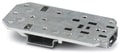
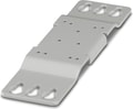 UWA 182/52 - Universal wall adapter for securely mounting the device in the event of strong vibrations. The device is screwed directly onto the mounting surface. The universal wall adapter is attached on the top/bottom.
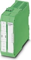 ME-MAX-NEF/QUINT20A - Filter for adherence to the EMC category EMC1 in shipbuilding for the QUINT-PS/1AC/24DC/20 power supply
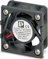 QUINT-PS/FAN/4 - The fan for QUINT-PS/1AC and .../3AC can be mounted without the need for tools or other accessories. By using the fan, optimum cooling is ensured at high ambient temperatures or if the mounting position is rotated.
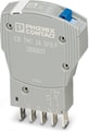
 PLT-SEC-T3-230-FM-UT - Type 2/3 surge protection, consisting of protective plug and base element with screw connection. For single-phase power supply network with integrated status indicator and remote signaling. Nominal voltage: 230 V AC/DC
 PLT-SEC-T3-24-FM-UT - Type 3 surge protection, consisting of protective plug and base element, with integrated status indicator and remote signaling for single-phase power supply networks. Nominal voltage: 24 V AC/DC


Why Proax for Phoenix Contact 2320898?
Proax is an authorized distributor of Phoenix Contact 2320898 and one of Phoenix Contact's largest distributors in North America. Our highly skilled in-house technical team is ready to assist with any technical needs.
Have a question in mind? to help you get the right product as quickly as possible for your project. We're always here to help!
Short Lead Time
Highly Trained Staff
Live Chat
Technical Support
Local Inventory
60+ Years Experience
Additional Information
| Pack Size | 1 |
Recommended
 QUINT-PS/1AC/24DC/20 - Primary-switched power supply unit QUINT POWER, Screw connection, DIN rail mounting, SFB Technology (Selective Fuse Breaking), input: 1-phase, output: 24 V DC / 20 A
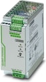 QUINT-PS/1AC/24DC/10 - Primary-switched power supply unit QUINT POWER, Screw connection, DIN rail mounting, SFB Technology (Selective Fuse Breaking), input: 1-phase, output: 24 V DC / 10 A
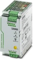 QUINT-PS/1AC/24DC/10/CO - Primary-switched power supply unit QUINT POWER, Screw connection, DIN rail mounting, SFB Technology (Selective Fuse Breaking), input: 1-phase, output: 24 V DC / 10 A
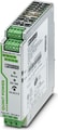 QUINT-PS/1AC/24DC/ 3.5 - Primary-switched power supply unit QUINT POWER, Screw connection, SFB Technology (Selective Fuse Breaking), input: 1-phase, output: 24 V DC / 3.5 A
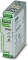 QUINT-PS/1AC/24DC/5 - Primary-switched power supply with SFB technology, 1 AC, output current 5 A
 QUINT-PS/1AC/12DC/20 - Primary-switched power supply unit QUINT POWER, Screw connection, SFB Technology (Selective Fuse Breaking), input: 1-phase, output: 12 V DC / 20 A
 Primary-switched QUINT POWER power supply for DIN rail mounting with SFB (Selective Fuse Breaking) Technology, input: 1-phase, output: 12 V DC/15 A
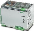 QUINT-PS/1AC/48DC/20 - Primary-switched power supply unit QUINT POWER, Screw connection, SFB Technology (Selective Fuse Breaking), input: 1-phase, output: 48 V DC / 20 A
 QUINT-PS/1AC/48DC/10 - Primary-switched power supply unit QUINT POWER, Screw connection, SFB Technology (Selective Fuse Breaking), input: 1-phase, output: 48 V DC / 10 A
 QUINT-PS/1AC/48DC/ 5 - Primary-switched power supply unit QUINT POWER, Pluggable screw connection, DIN rail mounting, SFB Technology (Selective Fuse Breaking), input: 1-phase, output: 48 V DC / 5 A
 Primary-switched QUINT POWER power supply for DIN rail mounting with SFB (Selective Fuse Breaking) Technology, input: 3-phase, output: 24 V DC/20 A
- QUINT-PS/3AC/24DC/20/CO - Primary-switched power supply unit QUINT POWER, Screw connection, SFB Technology (Selective Fuse Breaking), input: 3-phase, output: 24 V DC / 20 A
 QUINT-PS/3AC/24DC/10 - Primary-switched power supply unit QUINT POWER, Pluggable screw connection, SFB Technology (Selective Fuse Breaking), input: 3-phase, output: 24 V DC / 10 A
 QUINT-PS/3AC/24DC/40 - Primary-switched power supply unit QUINT POWER, Screw connection, DIN rail mounting, SFB Technology (Selective Fuse Breaking), input: 3-phase, output: 24 V DC / 40 A
 QUINT-PS/3AC/24DC/ 5 - Primary-switched power supply unit QUINT POWER, Pluggable screw connection, SFB Technology (Selective Fuse Breaking), input: 3-phase, output: 24 V DC / 5 A
 QUINT-PS/3AC/48DC/20 - Primary-switched power supply unit QUINT POWER, Screw connection, DIN rail mounting, SFB Technology (Selective Fuse Breaking), input: 3-phase, output: 48 V DC / 20 A
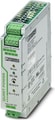 QUINT-PS/12DC/24DC/ 5 - Primary-switched QUINT DC/DC converter for DIN rail mounting with SFB (Selective Fuse Breaking) Technology, input: 12 V DC, output: 24 V DC/5 A