









































2900899
 Official Distributor
SKU
PHX2900899
MPN
UM-KS50/32MR/1/ADV551/SC/SO207
Weight
1.015 kg
Series UM-KS
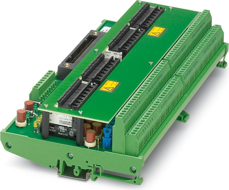
UM-KS50/32MR/1/ADV551/SC/SO207 - Relay Module
32-channel VARIOFACE relay module with screw connection and 50-pos. system connection. The power supply is designed redundantly, for Yokogawa ADV 551 card
Technical Specifications
Product properties
| No. of channels | 32 |
Insulation characteristics
| Insulation | Safe isolation, reinforced insulation |
Insulation characteristics: Air clearances and creepage distances, input/output
| Insulation | Safe isolation, reinforced insulation |
| Overvoltage category | III |
| Pollution degree | 2 |
Insulation characteristics: Air and creepage distances, output/output
| Insulation | Basic insulation |
| Overvoltage category | III |
| Pollution degree | 2 |
Air clearances and creepage distances, input/output
| Rated Insulation Voltage | 300 V |
| Rated surge voltage | 6 kV (1.2/50 μs) |
Air and creepage distances, output/output
| Rated Insulation Voltage | 300 V |
| Rated surge voltage | 4 kV (1.2/50 μs) |
Supported controller YOKOGAWA CS3000 CentumVP
| Suitable I/O card | ADV551 |
| Suitable I/O card | ADV561 |
Supported controller YOKOGAWA STARDOM
| Suitable I/O card | NFDV551 |
| Suitable I/O card | NFDV561 |
Input data
| Nominal input voltage UN | 24 V DC |
| Input voltage range in reference to UN | 0.8 ... 1.1 |
| Input voltage range | 19.2 V DC ... 26.4 V DC |
| Typical input current at UN | 9 mA (per channel) |
| Protective circuit | Damping diode, polarity protection; Damping diode, polarity protection diode |
| Protective circuit | Reverse polarity protection; Polarity protection diode |
| Operating voltage display | Green LED |
| Status display/channel | Yellow LED |
Switching
| Contact switching type | 1 N/O contact |
| Type of switch contact | Single contact |
| Contact Material | AgSnO |
| Maximum Switching Voltage | 230 V AC |
| Limiting Continuous Current | 2 A (Per channel, plug-in fuse (IEC 6012-3/IV, 2AT); for 100% ED 1 A per channel) |
| Maximum Inrush Current | 8 A (Supply, (V1+, V2+), pluggable fuse (UL 248-14, 250 V, 8AT)) |
| Min. switching current | 100 mA |
| Interrupting rating (ohmic load) max. | 48 W (at 24 V DC) |
| Interrupting rating (ohmic load) max. | 20 W (at 48 V DC) |
| Interrupting rating (ohmic load) max. | 18 W (at 60 V DC) |
| Interrupting rating (ohmic load) max. | 23 W (at 110 V DC) |
| Interrupting rating (ohmic load) max. | 40 W (at 220 V DC) |
| Interrupting rating (ohmic load) max. | 500 VA (for 250 V AC) |
Field level
| Connection Method | Screw connection |
| Conductor cross section rigid | 0.2 mm² ... 4 mm² |
| Conductor cross section flexible | 0.2 mm² ... 2.5 mm² |
| Conductor cross section AWG | 24 ... 12 |
Controller level
| Connection Method | Yokogawa KS-compatible |
| Number of Connections | 1 |
| Number of Positions | 50 |
| Tightening torque | 0.5 Nm |
Supply
| Connection Method | Screw connection |
| Number of Positions | 8 |
| Conductor cross section rigid | 0.2 mm² ... 4 mm² |
| Conductor cross section flexible | 0.2 mm² ... 2.5 mm² |
| Conductor cross section AWG | 24 ... 12 |
Signaling
| Status display present | Yes |
Dimensions
| Width | 267 mm |
| Height | 127.5 mm |
| Depth | 56.5 mm |
Ambient conditions
| Degree of Protection | IP00 |
| Degree of protection (Installation location) | ≥ IP54 (Installation location) |
| Ambient Temperature (Operation) | -20 °C ... 50 °C |
| Altitude | ≤ 2000 m |
Air clearances and creepage distances, input/output
| Standards/regulations | EN 61010-2-201 |
Air and creepage distances, output/output
| Standards/regulations | EN 61010-2-201 |
Mounting
| Mounting Type | DIN rail mounting |
| Mounting Position | any |
Notes
| Notes on operation | Observe the maximum switching capacity of the relays used |
| Notes on operation | Do not connect adjacent channels to SELV/ PELV and voltages dangerous to the touch. |
| Notes on operation | The necessary requirements for insulation (basic insulation or reinforced insulation) from adjacent modules (in DIN-rail direction) must be realized by applying suitable measures (e. g., partition plates). |
| Notes on operation | Adjacent channels are not suitable for switching different line conductors. |
| Notes on operation | For proper use, the specifications of the installation directive (see Downloads) must be observed. For applications or use with third-party products, the specifications, and the safety and warning instructions of the respective third-party manufacturer must also be met. |
Why Proax for Phoenix Contact 2900899?
Proax is an authorized distributor of Phoenix Contact 2900899 and one of Phoenix Contact's largest distributors in North America. Our highly skilled in-house technical team is ready to assist with any technical needs.
Have a question in mind? to help you get the right product as quickly as possible for your project. We're always here to help!
Short Lead Time
Highly Trained Staff
Live Chat
Technical Support
Local Inventory
60+ Years Experience
Additional Information
| Pack Size | 1 |
Recommended
 32-channel VARIOFACE relay module with screw connection and 50-pos. system connection. The power supply is designed redundantly, for Yokogawa ADV 151 card, module width: 232.5 mm
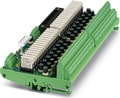 32-channel output relay module (1 N/O contact, optionally non-isolated) with screw connection, fuse (1 AT), and 50-pos. system connection. Suitable for the Yokogawa ADV 551 and ADV 561 cards.
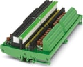 UM-KS50/32-MR/21/ADV151/SO207 - 32-channel input relay module with spring-cage connection and 50-pos. system connection. The coil side is secured and optionally non-isolated. Suitable for the Yokogawa ADV 151 und ADV 161 cards.
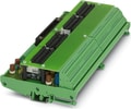 UM-KS50/32-MR/21/ADV551/SO207 - 32-channel output relay module (1 N/O contact, optionally non-isolated) with spring-cage connection, fuse (2 AT), and 50-pos. system connection. Suitable for the Yokogawa ADV 551 and ADV 561 cards.