


SKU
MPN
IOA-PSR-PS22-1NO-1NC-24DC
Weight
0.136 kg
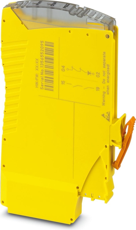
IOA-PSR-PS22-1NO-1NC-24DC - Coupling relay
Plug-in SIL coupling relay as an input/output accessory for VIP base module, SIL 3 high- and low-demand applications, safe-state-off, couples digital output signals to the periphery, one enabling current path, one confirmation current path, test pulse filter
- Up to SIL 3 in accordance with IEC 61508
- Force-guided contacts in accordance with EN 50205
- Easy proof test according to IEC 61508 thanks to integrated signal contact
- Easy proof test according to IEC 61508
- Long service life thanks to filtering of controller test pulses
- 1 enabling current path, 1 diagnostic current path
- Couples digital output signals from failsafe controllers to I/O devices (valves, etc.) for electrical isolation and power adaptation
Technical Specifications
Product properties
| Product family | PSRmini |
| Application | Safe switch off |
| Application | High demand |
| Application | Low demand |
| Application | Ex |
| Relay type | Electromechanical relay with force-guided contacts in accordance with IEC/EN 61810-3 |
Times
| Typ. starting time with Us | 150 ms (when controlled via pins 05/06) |
| Typical release time | 30 ms (when controlled via pins 05/06) |
| Recovery time | 500 ms |
Electrical properties
| Maximum power dissipation for nominal condition | 1.86 W (at UB = 30 V DC, UBD = 30 V DC, IL = 9 A²) |
| Nominal operating mode | 100% operating factor |
Air clearances and creepage distances between the power circuits
| Rated Insulation Voltage | 250 V AC |
| Rated surge voltage/insulation | Basic insulation 4 kV between all current paths and housing |
| Rated surge voltage/insulation | Safe isolation, 6 kV reinforced insulation from the control circuit (05/06) and diagnostics circuit (03/04/02) to the enabling current path (15/19) |
Supply
| Rated control circuit supply voltage US | 19.5 V DC ... 30 V DC |
| Rated control circuit supply voltage US | 24 V DC -20 % / +25 % |
| Rated control supply current IS | typ. 25 mA |
| Power consumption at US | typ. 0.77 W |
| Inrush Current | typ. 100 mA (Δt < 50 ms at Us) |
| Filter time | max. 3 ms (at pins 05/06 in the event of voltage dips at Us) |
| Filter time | max. 3 ms (at pins 05/06; low test pulse width) |
| Filter time | ≥ 50 ms (at pins 05/06; low test pulse width) |
| Filter time | max. 17 ms (at pins 05/06; high test pulse width) |
| Filter time | ≥ 600 ms (at pins 05/06; high test pulse width) |
| Diagnostic supply voltage UD | 24 V DC -20 % / +25 % (at pin 04) |
| Input current at UD | 7 mA (at pins 04/03 for UD; + 100 mA depending on load at pin 02) |
| Inrush current at UD | typ. 200 mA (Δt < 1 ms; at pins 04/03 for UD) |
| Protective circuit | Surge protection; 35 V suppressor diode (pins 05/06)33 V suppressor diode (pins 04/03)35 V suppressor diode (pins 02/03) |
| Protective circuit | Polarity reversal protection for rated control circuit supply voltage and diagnostic supply voltage |
Relay: Enabling current path
| Output description | safety-related N/O contacts |
| Number of Outputs | 1 (undelayed) |
| Contact switching type | 1 enabling current path |
| Contact Material | AgSnO2 |
| Switching voltage | min. 12 V AC/DC |
| Switching voltage | max. 230 V AC/DC (Observe the load curve) |
| Switching capacity | min. 60 mW |
| Inrush Current | min. 3 mA |
| Inrush Current | max. 3 A |
| Switching capacity in accordance with IEC 60947-5-1 | 3 A (24 V (DC13)) |
| Switching capacity in accordance with IEC 60947-5-1 | 3 A (230 V (AC15)) |
| Limiting Continuous Current | 3 A (observe derating) |
| Sq. Total current | 9 A2 (observe derating) |
| Mechanical service life | 10x 10⁶ cycles |
| Output fuse | 3 A gL/gG |
Relay: Confirmation current path
| Output description | Safety-related N/C contacts |
| Number of Outputs | 1 (undelayed) |
| Contact switching type | 1 confirmation current path |
| Contact Material | AgCuNi, + Au |
| Switching voltage | min. 19.2 V DC |
| Switching voltage | max. 30 V DC |
| Switching capacity | min. 20 mW |
| Inrush Current | min. 1 mA |
| Inrush Current | max. 100 mA |
| Limiting Continuous Current | 100 mA |
| Output fuse | 150 mA Fast-blow |
Connection technology
| pluggable | yes |
Conductor connection
| Connection Method | Pluggable onto VIP base module |
Signaling
| Status display | 2 x LED bi-color (green, red) |
Dimensions
| Width | 10 mm |
| Height | 75 mm |
| Depth | 112 mm |
Material specifications
| Color (Housing) | yellow (RAL 1018) |
| Housing Material | PA 6.6 |
Safety data
| Stop category | 0 |
Safety data: EN ISO 13849
| Category | 4 |
| Performance level (PL) | e |
Safety data: EN 50156-2
| Safety Integrity Level (SIL) | 3 (Reference IEC 61508) |
Safety data: IEC 61508 - High demand
| Safety Integrity Level (SIL) | 3 (< 15% of the overall SIL) |
Safety data
| Safety Integrity Level (SIL) | 3 (< 15% of the overall SIL) |
Safety data: IEC 61508 - Low demand
| Safety Integrity Level (SIL) | 3 (< 15% of the overall SIL) |
Safety data
| Safety Integrity Level (SIL) | 3 (< 15% of the overall SIL) |
Safety data: IEC 61508 - Low demand
| Safety Integrity Level (SIL) | 3 (< 15% of the overall SIL) |
Safety data: EN IEC 62061
| Safety Integrity Level (SIL) | 3 |
Ambient conditions
| Degree of Protection | IP20 |
| Min. degree of protection of inst. location | IP54 |
| Ambient Temperature (Operation) | -40 °C ... 70 °C (observe derating) |
| Ambient temperature (storage/transport) | -40 °C ... 85 °C |
| Maximum altitude | ≤ 2000 m (Above sea level) |
| Max. permissible humidity (storage/transport) | 75 % (on average, 85% infrequently, non-condensing) |
| Max. permissible relative humidity (operation) | 75 % (on average, 85% infrequently, non-condensing) |
| Shock | 15 g (in the event of continuous stress caused by shock, contact reactions are possible.) |
| Vibration (Operation) | 10 Hz ... 150 Hz, 2g |
ATEX
| Identification | II 3G Ex ec nC IIC T4 Gc |
| Certificate | Sira 17ATEX4293X |
IECEx
| Identification | Ex ec nC IIC T4 Gc |
| Certificate | IECEx SIR 17.0078X |
UL, USA/Canada
| Identification | Class I, Div. 2, Groups A, B, C, D T4 |
| Identification | Class I, Zone 2, Group IIC T4 |
CSA, USA/Canada
| Identification | Class I, Div. 2, Groups A, B, C, D T4 |
| Identification | Class I, Zone 2, AEx ec nC IIC T4 Gc |
| Identification | Ex ec nC IIC T4 Gc |
CE
| Identification | CE-compliant |
Air clearances and creepage distances between the power circuits
| Standards/regulations | EN 60947-1, EN 60079-0, EN 60079-15 |
Mounting
| Mounting Type | Plug-in mounting |
| Assembly instructions | See derating curve |
| Mounting Position | vertical or horizontal |
Accessories

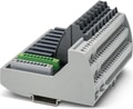 VIP/S/MC/BASE 1-8/L/EX - 8-channel VIP I/O marshalling base element for universal use. All connections as screw connection technology. With the COMBICON connector, compatible with the Honeywell C300 and RUSIO series. Marking for channels 1–8.
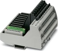
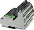 VIP/S/MC/BASE 9-16/L/EX - 8-channel VIP I/O marshalling base element for universal use. All connections as screw connection technology. With the COMBICON connector, compatible with the Honeywell C300 and RUSIO series. Marking for channels 9–16.
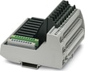 VIP/S/MC/BASE 17-24/L/EX - 8-channel VIP I/O marshalling base element for universal use. All connections as screw connection technology. With the COMBICON connector, compatible with the Honeywell C300 and RUSIO series. Marking for channels 17–24.
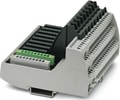 VIP/S/MC/BASE 25-32/L/EX - 8-channel VIP I/O marshalling base element for universal use. All connections as screw connection technology. With the COMBICON connector, compatible with the Honeywell C300 and RUSIO series. Marking for channels 25–32.
- VIP/S/MC/BASE 1-8/L/C/EX - 8-channel VIP I/O marshalling base element for universal use. All connections as screw connection technology. With the COMBICON connector, compatible with the Honeywell C300 and RUSIO series. Marking for channels 1–8 and painting.
- VIP/S/MC/BASE 9-16/L/C/EX - 8-channel VIP I/O marshalling base element for universal use. All connections as screw connection technology. With the COMBICON connector, compatible with the Honeywell C300 and RUSIO series. Marking for channels 9–16 and painting.
 VIP/S/MC/BASE 17-24/L/C/EX - 8-channel VIP I/O marshalling base element for universal use. All connections as screw connection technology. With the COMBICON connector, compatible with the Honeywell C300 and RUSIO series. Marking for channels 17–24 and painting.
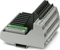 VIP/S/MC/BASE 25-32/L/C/EX - 8-channel VIP I/O marshalling base element for universal use. All connections as screw connection technology. With the COMBICON connector, compatible with the Honeywell C300 and RUSIO series. Marking for channels 25–32 and painting.
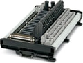 16-channel VIP I/O marshalling base element for universal use. Plug-in field and supply terminals available as accessories. Either with screw or Push-in connection technology. Compatible with the Tricon CX DCS series (D-SUB 50).
Why Proax for Phoenix Contact 2702971?
Proax is an authorized distributor of Phoenix Contact 2702971 and one of Phoenix Contact's largest distributors in North America. Our highly skilled in-house technical team is ready to assist with any technical needs.
Have a question in mind? to help you get the right product as quickly as possible for your project. We're always here to help!
Short Lead Time
Highly Trained Staff
Live Chat
Technical Support
Local Inventory
60+ Years Experience
Additional Information
| Pack Size | 1 |