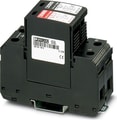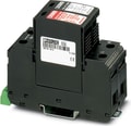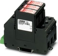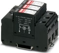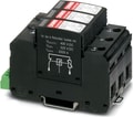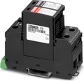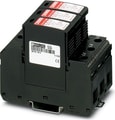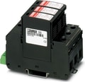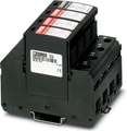
2800670
 Official Distributor
SKU
PHX2800670
MPN
VAL-MS-T1/T2 175/12.5/3+1-FM
Weight
0.58 kg
Series VAL-MS-T1
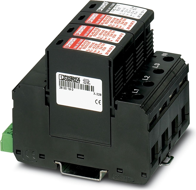
VAL-MS-T1/T2 175/12.5/3+1-FM - Lightning/surge arrester type 1/2
Universal varistor-based plug-in lightning/surge arrester for 3-phase power supply networks with separate N and PE (5-conductor system: L1, L2, L3, N, PE), for Lightning Protection Levels III and IV, with remote indication contact.
Technical Specifications
General
| Note | Nominal voltage UN = 120 V AC/240 V AC split-phase (separate GND) |
Product properties
| Product family | VALVETRAB MS |
| IEC test classification | I / II |
| IEC test classification | T1 / T2 |
| EN type | T1 / T2 |
| IEC power supply system | TT |
| IEC power supply system | TN-C |
| IEC power supply system | TN-S |
| Type | DIN rail module, two-section, divisible |
| Surge protection fault message | Optical, remote indicator contact |
Insulation characteristics
| Overvoltage category | III |
| Pollution degree | 2 |
Electrical properties
| Nominal frequency fN | 50 Hz (60 Hz) |
| Nominal voltage UN | 120 V AC |
Indicator/remote signaling
| Connection name | Remote fault indicator contact |
| Switching function | Changeover contact |
| Operating Voltage | 5 V AC ... 250 V AC |
| Operating Voltage | 30 V DC |
| Operating current | 5 mA AC ... 1.5 A AC |
| Operating current | 1 A DC |
Connection data
| Connection Method | Screw connection |
| Screw thread | M5 |
| Tightening torque | 4.5 Nm |
| Stripping length | 16 mm |
| Conductor cross section flexible | 1.5 mm² ... 25 mm² |
| Conductor cross section rigid | 1.5 mm² ... 35 mm² |
| Conductor cross section AWG | 15 ... 2 |
Remote fault indicator contact
| Connection Method | Screw connection |
| Screw thread | M2 |
| Tightening torque | 0.25 Nm |
| Stripping length | 7 mm |
| Conductor cross section flexible | 0.14 mm² ... 1.5 mm² |
| Conductor cross section rigid | 0.14 mm² ... 1.5 mm² |
| Conductor cross section AWG | 28 ... 16 |
Dimensions
| Width | 71.2 mm |
| Height | 99 mm |
| Depth | 77.5 mm |
| Horizontal pitch | 4 Div. |
Material specifications
| Flammability rating according to UL 94 | V-0 |
| CTI value of material | 600 |
| Insulating material | PA 6.6/PBT |
| Material group | I |
| Housing Material | PA 6.6 |
| Housing Material | PBT |
Mechanical data
| Open side panel | No |
Protective circuit
| Mode of protection | L-N |
| Mode of protection | L-PE |
| Mode of protection | N-PE |
| Direction of action | 3L-N & N-PE |
| Nominal voltage UN | 120/208 V AC (TN-S) |
| Nominal voltage UN | 120/208 V AC (TT) |
| Nominal frequency fN | 50 Hz (60 Hz) |
| Maximum continuous operating voltage UC (L-N) | 175 V AC |
| Maximum continuous operating voltage UC (L-PE) | 175 V AC |
| Maximum continuous operating voltage UC (N-PE) | 264 V AC |
| Rated load current IL | 80 A |
| Residual current IPE | ≤ 5 µA |
| Standby power consumption PC | ≤ 420.00 mVA |
| Nominal discharge current In (8/20) µs (L-N) | 12.5 kA |
| Nominal discharge current In (8/20) µs (L-PE) | 12.5 kA |
| Nominal discharge current In (8/20) µs (N-PE) | 50 kA |
| Maximum discharge current Imax (8/20) µs | 50 kA |
| Impulse discharge current (10/350) µs (L-N), charge | 6.25 As |
| Impulse discharge current (10/350) µs (L-N), specific energy | 39 kJ/Ω |
| Impulse discharge current (10/350) µs (L-N), peak current value Iimp | 12.5 kA |
| Impulse discharge current (10/350) µs (L-PE), charge | 6.25 As |
| Impulse discharge current (10/350) µs (L-PE), specific energy | 39 kJ/Ω |
| Impulse discharge current (10/350) µs (L-PE), peak current value Iimp | 12.5 kA |
| Impulse discharge current (10/350) µs (N-PE), charge | 25 As |
| Impulse discharge current (10/350) µs (N-PE), specific energy | 625 kJ/Ω |
| Impulse discharge current (10/350) µs (N-PE), peak current value Iimp | 50 kA |
| Total discharge current Itotal (8/20) µs | 50 kA |
| Total discharge current Itotal (10/350) µs | 50 kA |
| Follow current interrupt rating Ifi (N-PE) | 100 A (264 V AC) |
| Short-circuit current rating ISCCR | 25 kA |
| Voltage protection level Up (L-N) | ≤ 0.8 kV |
| Voltage protection level Up (L-PE) | ≤ 2 kV |
| Voltage protection level Up (N-PE) | ≤ 1.7 kV |
| Residual voltage Ures (L-N) | ≤ 0.8 kV (at In) |
| Residual voltage Ures (L-N) | ≤ 0.75 kV (at 10 kA) |
| Residual voltage Ures (L-N) | ≤ 0.65 kV (at 5 kA) |
| Residual voltage Ures (L-N) | ≤ 0.6 kV (at 3 kA) |
| Residual voltage Ures (L-PE) | ≤ 2 kV (at In) |
| Residual voltage Ures (L-PE) | ≤ 1.5 kV (at 10 kA) |
| Residual voltage Ures (L-PE) | ≤ 1.4 kV (at 5 kA) |
| Residual voltage Ures (L-PE) | ≤ 1.3 kV (at 3 kA) |
| Residual voltage Ures (N-PE) | ≤ 0.6 kV (at In) |
| Residual voltage Ures (N-PE) | ≤ 0.5 kV (at 10 kA) |
| Residual voltage Ures (N-PE) | ≤ 0.5 kV (at 5 kA) |
| Residual voltage Ures (N-PE) | ≤ 0.4 kV (at 3 kA) |
| TOV behavior at UT (L-N) | 208 V AC (5 s / withstand mode) |
| TOV behavior at UT (L-N) | 229 V AC (120 min / withstand mode) |
| TOV behavior at UT (N-PE) | 1200 V AC (200 ms / withstand mode) |
| Response time tA (L-N) | ≤ 25 ns |
| Response time tA (L-PE) | ≤ 100 ns |
| Response time tA (N-PE) | ≤ 100 ns |
| Max. backup fuse with V-type through wiring | 80 A (gG - 16 mm²) |
| Max. backup fuse with branch wiring | 160 A (gG) |
Ambient conditions
| Degree of Protection | IP20 (only when all terminal points are used) |
| Ambient Temperature (Operation) | -40 °C ... 80 °C |
| Ambient temperature (storage/transport) | -40 °C ... 80 °C |
| Altitude | ≤ 2000 m (amsl) |
| Permissible humidity (operation) | 5 % ... 95 % |
| Shock (operation) | 30g (Half-sine / 11 ms / 3x ±X, ±Y, ±Z) |
| Vibration (Operation) | 7.5g (10 ... 500 Hz / 2.5 h / X, Y, Z) |
UL specifications
| Maximum continuous operating voltage MCOV (L-L) | 350 V AC |
| Maximum continuous operating voltage MCOV (L-N) | 175 V AC |
| Maximum continuous operating voltage MCOV (L-G) | 175 V AC |
| Maximum continuous operating voltage MCOV (N-G) | 264 V AC |
| Nominal discharge current In (L-L) | 20 kA |
| Nominal discharge current In (L-N) | 20 kA |
| Nominal discharge current In (L-G) | 20 kA |
| Nominal discharge current In (N-G) | 20 kA |
| Mode of protection | L-L |
| Mode of protection | L-N |
| Mode of protection | L-G |
| Mode of protection | N-G |
| Nominal Voltage | 120/208 V AC |
| Power distribution system | Wye |
| Nominal frequency | 50/60 Hz |
| Measured limiting voltage MLV (L-L) | 2800 V |
| Measured limiting voltage MLV (L-N) | 2200 V |
| Measured limiting voltage MLV (L-G) | 3160 V |
| Measured limiting voltage MLV (N-G) | 2600 V |
| SPD Type | 4CA |
UL indicator/remote signaling
| Operating Voltage | 125 V AC |
| AC operating current | 1 A AC |
UL connection data
| Tightening torque | 30 lbf-in. |
| Conductor cross section AWG | 10 ... 2 |
Standards and Regulations
| Standards/specifications | IEC 61643-11 |
| Note | 2011 |
| Standards/specifications | EN 61643-11 |
| Note | 2012 |
Mounting
| Mounting Type | DIN rail: 35 mm |
Why Proax for Phoenix Contact 2800670?
Proax is an authorized distributor of Phoenix Contact 2800670 and one of Phoenix Contact's largest distributors in North America. Our highly skilled in-house technical team is ready to assist with any technical needs.
Have a question in mind? to help you get the right product as quickly as possible for your project. We're always here to help!
Short Lead Time
Highly Trained Staff
Live Chat
Technical Support
Local Inventory
60+ Years Experience
Additional Information
| Pack Size | 1 |
Recommended


