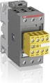









































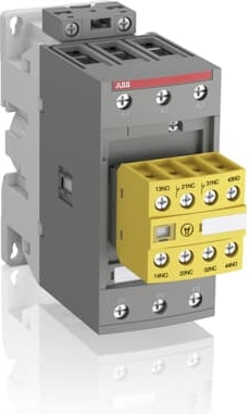
AFS65-30-22-11
 Official Distributor
By ABB
AFS contactors for safety applications
AFS contactors are specifically designed to enhance safety in machine applications. Featuring factory-mounted contact blocks with mechanically linked and mirror contacts, these contactors ensure reliable monitoring and control of circuits. With ABB’s comprehensive safety component range, building protection systems becomes more straightforward and efficient.
Main Benefits:
Safety Compliance: Meets major safety standards (EN ISO 13849 and EN 62061) for secure machinery and equipment use.
Guaranteed Status: Factory-mounted auxiliary contact blocks ensure accurate contactor status monitoring.
Easy Identification: Distinct yellow housing simplifies safety chain recognition.
Streamlined Safety Calculations: Safety values available in FSDT and Sistema tools for easier safety level assessments.
Main Features:
High Power Handling:
Up to 400 kW at 400 V AC-3
Up to 600 hp at 480 V
Up to 1050 A at 690 V AC-1
Up to 900 A for general use
Certified Safety Contacts: Mirror and mechanically linked contacts with third-party certification.
Fast Response: Opening times as low as 20 ms in certain models with PLC interfaces.
Precision Switching: Low-energy auxiliary contacts with a minimum switching capacity of 12 V, 3 mA (10⁻⁷).
Built-in Protection: Integrated surge suppression for enhanced safety.
Dimensions
| Product Net Width | 55 mm |
| Product Net Depth / Length | 144 mm |
| Product Net Height | 125.5 mm |
| Product Net Weight | 1.02 kg |
| Dimension Diagram | DNV_TAE00001AF-4 |
Technical
| Number of Main Contacts NO | 3 |
| Number of Main Contacts NC | 0 |
| Number of Auxiliary Contacts NO | 2 |
| Number of Auxiliary Contacts NC | 2 |
| Number of Poles | 3P |
| Standards | IEC/EN 60947-1, IEC/EN 60947-4-1, UL 60335-2-40 LZGH2 A2L, UL 60947-1, UL 60947-4-1, CSA C22.2 No. 60335-2-40 LZGH2 A2L, CSA C22.2 No. 60947-1:22, CSA C22.2 No. 60947-4-1:22 |
| Rated Operational Voltage | Auxiliary Circuit 690 V |
| Rated Operational Voltage | Main Circuit 690 V |
| Rated Frequency (f) | Auxiliary Circuit 50 / 60 Hz |
| Rated Frequency (f) | Control Circuit 50 / 60 Hz |
| Rated Frequency (f) | Main Circuit 50 / 60 Hz |
| Conventional Free-air Thermal Current (Ith) | acc. to IEC 60947-4-1, Open Contactors Θ = 40 °C 105 A |
| Conventional Free-air Thermal Current (Ith) | acc. to IEC 60947-5-1, Θ = 40 °C 16 A |
| Rated Operational Current AC-1 (Ie) | (690 V) 40 °C 105 A |
| Rated Operational Current AC-1 (Ie) | (690 V) 60 °C 90 A |
| Rated Operational Current AC-1 (Ie) | (690 V) 70 °C 80 A |
| Rated Operational Current AC-3 (Ie) | (415 V) 60 °C 65 A |
| Rated Operational Current AC-3 (Ie) | (440 V) 60 °C 65 A |
| Rated Operational Current AC-3 (Ie) | (500 V) 60 °C 55 A |
| Rated Operational Current AC-3 (Ie) | (690 V) 60 °C 39 A |
| Rated Operational Current AC-3 (Ie) | (380 / 400 V) 60 °C 65 A |
| Rated Operational Current AC-3 (Ie) | (220 / 230 / 240 V) 60 °C 65 A |
| Rated Operational Current AC-3e (Ie) | (415 V) 60 °C 65 A |
| Rated Operational Current AC-3e (Ie) | (440 V) 60 °C 65 A |
| Rated Operational Current AC-3e (Ie) | (500 V) 60 °C 55 A |
| Rated Operational Current AC-3e (Ie) | (690 V) 60 °C 39 A |
| Rated Operational Current AC-3e (Ie) | (380 / 400 V) 60 °C 65 A |
| Rated Operational Current AC-3e (Ie) | (220 / 230 / 240 V) 60 °C 65 A |
| Rated Operational Current AC-15 (Ie) | (500 V) 2 A |
| Rated Operational Current AC-15 (Ie) | (690 V) 2 A |
| Rated Operational Current AC-15 (Ie) | (24 / 127 V) 6 A |
| Rated Operational Current AC-15 (Ie) | (220 / 240 V) 4 A |
| Rated Operational Current AC-15 (Ie) | (400 / 440 V) 3 A |
| Rated Operational Current DC-1 (Ie) | (110 V) 2 Poles in Series, 40 °C 105 A |
| Rated Operational Current DC-1 (Ie) | (110 V) 2 Poles in Series, 60 °C 90 A |
| Rated Operational Current DC-1 (Ie) | (110 V) 2 Poles in Series, 70 °C 80 A |
| Rated Operational Current DC-1 (Ie) | (110 V) 3 Poles in Series, 40 °C 105 A |
| Rated Operational Current DC-1 (Ie) | (110 V) 3 Poles in Series, 60 °C 90 A |
| Rated Operational Current DC-1 (Ie) | (110 V) 3 Poles in Series, 70 °C 80 A |
| Rated Operational Current DC-1 (Ie) | (220 V) 3 Poles in Series, 40 °C 105 A |
| Rated Operational Current DC-1 (Ie) | (220 V) 3 Poles in Series, 60 °C 90 A |
| Rated Operational Current DC-1 (Ie) | (220 V) 3 Poles in Series, 70 °C 80 A |
| Rated Operational Current DC-1 (Ie) | (72 V) 1-Pole, 40 °C 105 A |
| Rated Operational Current DC-1 (Ie) | (72 V) 1-Pole, 60 °C 90 A |
| Rated Operational Current DC-1 (Ie) | (72 V) 1-Pole, 70 °C 80 A |
| Rated Operational Current DC-1 (Ie) | (72 V) 2 Poles in Series, 40 °C 105 A |
| Rated Operational Current DC-1 (Ie) | (72 V) 2 Poles in Series, 60 °C 90 A |
| Rated Operational Current DC-1 (Ie) | (72 V) 2 Poles in Series, 70 °C 80 A |
| Rated Operational Current DC-1 (Ie) | (72 V) 3 Poles in Series, 40 °C 105 A |
| Rated Operational Current DC-1 (Ie) | (72 V) 3 Poles in Series, 60 °C 90 A |
| Rated Operational Current DC-1 (Ie) | (72 V) 3 Poles in Series, 70 °C 80 A |
| Rated Operational Current DC-3 (Ie) | (110 V) 2 Poles in Series, 40 °C 105 A |
| Rated Operational Current DC-3 (Ie) | (110 V) 2 Poles in Series, 60 °C 90 A |
| Rated Operational Current DC-3 (Ie) | (110 V) 2 Poles in Series, 70 °C 80 A |
| Rated Operational Current DC-3 (Ie) | (110 V) 3 Poles in Series, 40 °C 105 A |
| Rated Operational Current DC-3 (Ie) | (110 V) 3 Poles in Series, 60 °C 90 A |
| Rated Operational Current DC-3 (Ie) | (110 V) 3 Poles in Series, 70 °C 80 A |
| Rated Operational Current DC-3 (Ie) | (220 V) 3 Poles in Series, 40 °C 105 A |
| Rated Operational Current DC-3 (Ie) | (220 V) 3 Poles in Series, 60 °C 90 A |
| Rated Operational Current DC-3 (Ie) | (220 V) 3 Poles in Series, 70 °C 80 A |
| Rated Operational Current DC-3 (Ie) | (72 V) 1-Pole, 40 °C 105 A |
| Rated Operational Current DC-3 (Ie) | (72 V) 1-Pole, 60 °C 90 A |
| Rated Operational Current DC-3 (Ie) | (72 V) 1-Pole, 70 °C 80 A |
| Rated Operational Current DC-3 (Ie) | (72 V) 2 Poles in Series, 40 °C 105 A |
| Rated Operational Current DC-3 (Ie) | (72 V) 2 Poles in Series, 60 °C 90 A |
| Rated Operational Current DC-3 (Ie) | (72 V) 2 Poles in Series, 70 °C 80 A |
| Rated Operational Current DC-3 (Ie) | (72 V) 3 Poles in Series, 40 °C 105 A |
| Rated Operational Current DC-3 (Ie) | (72 V) 3 Poles in Series, 60 °C 90 A |
| Rated Operational Current DC-3 (Ie) | (72 V) 3 Poles in Series, 70 °C 80 A |
| Rated Operational Current DC-5 (Ie) | (110 V) 2 Poles in Series, 40 °C 105 A |
| Rated Operational Current DC-5 (Ie) | (110 V) 2 Poles in Series, 60 °C 90 A |
| Rated Operational Current DC-5 (Ie) | (110 V) 2 Poles in Series, 70 °C 80 A |
| Rated Operational Current DC-5 (Ie) | (110 V) 3 Poles in Series, 40 °C 105 A |
| Rated Operational Current DC-5 (Ie) | (110 V) 3 Poles in Series, 60 °C 90 A |
| Rated Operational Current DC-5 (Ie) | (110 V) 3 Poles in Series, 70 °C 80 A |
| Rated Operational Current DC-5 (Ie) | (220 V) 3 Poles in Series, 40 °C 105 A |
| Rated Operational Current DC-5 (Ie) | (220 V) 3 Poles in Series, 60 °C 90 A |
| Rated Operational Current DC-5 (Ie) | (220 V) 3 Poles in Series, 70 °C 80 A |
| Rated Operational Current DC-5 (Ie) | (72 V) 1-Pole, 40 °C 105 A |
| Rated Operational Current DC-5 (Ie) | (72 V) 1-Pole, 60 °C 90 A |
| Rated Operational Current DC-5 (Ie) | (72 V) 1-Pole, 70 °C 80 A |
| Rated Operational Current DC-5 (Ie) | (72 V) 2 Poles in Series, 40 °C 105 A |
| Rated Operational Current DC-5 (Ie) | (72 V) 2 Poles in Series, 60 °C 90 A |
| Rated Operational Current DC-5 (Ie) | (72 V) 2 Poles in Series, 70 °C 80 A |
| Rated Operational Current DC-5 (Ie) | (72 V) 3 Poles in Series, 40 °C 105 A |
| Rated Operational Current DC-5 (Ie) | (72 V) 3 Poles in Series, 60 °C 90 A |
| Rated Operational Current DC-5 (Ie) | (72 V) 3 Poles in Series, 70 °C 80 A |
| Rated Operational Current DC-13 (Ie) | (24 V) 6 A / 144 W |
| Rated Operational Current DC-13 (Ie) | (48 V) 2.8 A / 134 W |
| Rated Operational Current DC-13 (Ie) | (72 V) 1 A / 72 W |
| Rated Operational Current DC-13 (Ie) | (110 V) 1.1 A / 121 W |
| Rated Operational Current DC-13 (Ie) | (125 V) 0.55 A / 69 W |
| Rated Operational Current DC-13 (Ie) | (220 V) 0.27 A / 60 W |
| Rated Operational Current DC-13 (Ie) | (250 V) 0.27 A / 68 W |
| Rated Operational Current DC-13 (Ie) | (400 V) 0.15 A / 60 W |
| Rated Operational Current DC-13 (Ie) | (500 V) 0.13 A / 65 W |
| Rated Operational Current DC-13 (Ie) | (600 V) 0.1 A / 60 W |
| Rated Operational Power AC-3 (Pe) | (400 V) 30 kW |
| Rated Operational Power AC-3 (Pe) | (415 V) 37 kW |
| Rated Operational Power AC-3 (Pe) | (440 V) 37 kW |
| Rated Operational Power AC-3 (Pe) | (500 V) 37 kW |
| Rated Operational Power AC-3 (Pe) | (690 V) 37 kW |
| Rated Operational Power AC-3 (Pe) | (380 / 400 V) 30 kW |
| Rated Operational Power AC-3 (Pe) | (220 / 230 / 240 V) 18.5 kW |
| Rated Operational Power AC-3e (Pe) | (415 V) 37 kW |
| Rated Operational Power AC-3e (Pe) | (440 V) 37 kW |
| Rated Operational Power AC-3e (Pe) | (500 V) 37 kW |
| Rated Operational Power AC-3e (Pe) | (690 V) 37 kW |
| Rated Operational Power AC-3e (Pe) | (380 / 400 V) 30 kW |
| Rated Operational Power AC-3e (Pe) | (220 / 230 / 240 V) 18.5 kW |
| Rated Short-time Withstand Current Low Voltage (Icw) | at 40 °C Ambient Temp, in Free Air, from a Cold State 10 s 600 A |
| Rated Short-time Withstand Current Low Voltage (Icw) | at 40 °C Ambient Temp, in Free Air, from a Cold State 15 min 110 A |
| Rated Short-time Withstand Current Low Voltage (Icw) | at 40 °C Ambient Temp, in Free Air, from a Cold State 1 min 250 A |
| Rated Short-time Withstand Current Low Voltage (Icw) | at 40 °C Ambient Temp, in Free Air, from a Cold State 1 s 1000 A |
| Rated Short-time Withstand Current Low Voltage (Icw) | at 40 °C Ambient Temp, in Free Air, from a Cold State 30 s 350 A |
| Rated Short-time Withstand Current Low Voltage (Icw) | for 0.1 s 140 A |
| Rated Short-time Withstand Current Low Voltage (Icw) | for 1 s 100 A |
| Maximum Breaking Capacity | cos phi=0.45 (cos phi=0.35 for Ie > 100 A) at 440 V 950 A |
| Maximum Breaking Capacity | cos phi=0.45 (cos phi=0.35 for Ie > 100 A) at 690 V 600 A |
| Rated Insulation Voltage (Ui) | acc. to IEC 60947-4-1 690 V |
| Rated Insulation Voltage (Ui) | acc. to IEC 60947-5-1 690 V |
| Rated Insulation Voltage (Ui) | acc. to UL/CSA 600 V |
| Rated Impulse Withstand Voltage (Uimp) | 6 kV |
| Maximum Electrical Switching Frequency | (AC-1) 600 cycles per hour |
| Maximum Electrical Switching Frequency | (AC-15) 1200 cycles per hour |
| Maximum Electrical Switching Frequency | (AC-2 / AC-4) 150 cycles per hour |
| Maximum Electrical Switching Frequency | (AC-3) 1200 cycles per hour |
| Maximum Electrical Switching Frequency | (DC-13) 900 cycles per hour |
| Maximum Mechanical Switching Frequency | 3600 cycles per hour |
| Rated Control Circuit Voltage (Uc) | 50 Hz 24 ... 60 V |
| Rated Control Circuit Voltage (Uc) | 60 Hz 24 ... 60 V |
| Rated Control Circuit Voltage (Uc) | DC Operation 20 ... 60 V |
| Power Loss | at 6 A per Pole 0.1 W |
| Power Loss | at Rated Operating Conditions AC-1 per Pole 7 W |
| Power Loss | at Rated Operating Conditions AC-3 per Pole 2.7 W |
| Operate Time | Between Coil De-energization and NC Contact Closing 19 ... 105 ms |
| Operate Time | Between Coil De-energization and NO Contact Opening 17 ... 100 ms |
| Operate Time | Between Coil Energization and NC Contact Opening 38 ... 95 ms |
| Operate Time | Between Coil Energization and NO Contact Closing 42 ... 100 ms |
| Mounting on DIN Rail | TH35-15 (35 x 15 mm Mounting Rail) acc. to IEC 60715 |
| Mounting on DIN Rail | TH35-7.5 (35 x 7.5 mm Mounting Rail) acc. to IEC 60715 |
| Mounting by Screws (not supplied) | 2 x M4 or 2 x M6 Screws Placed Diagonally |
| Connecting Capacity Main Circuit | Flexible with Ferrule 1/2x 4 ... 35 mm² |
| Connecting Capacity Main Circuit | Flexible with Insulated Ferrule 1/2x 4 ... 35 mm² |
| Connecting Capacity Main Circuit | Rigid Stranded 1/2x 6 ... 35 mm² |
| Connecting Capacity Auxiliary Circuit | Flexible with Ferrule 1/2x 0.75 ... 2.5 mm² |
| Connecting Capacity Auxiliary Circuit | Flexible with Insulated Ferrule 2x 0.75 ... 1.5 mm² |
| Connecting Capacity Auxiliary Circuit | Flexible with Insulated Ferrule 1x 0.75 ... 2.5 mm² |
| Connecting Capacity Auxiliary Circuit | Rigid 1/2x 1 ... 2.5 mm² |
| Connecting Capacity Control Circuit | Flexible with Ferrule 1/2x 0.75 ... 2.5 mm² |
| Connecting Capacity Control Circuit | Flexible with Insulated Ferrule 1x 0.75 ... 2.5 mm² |
| Connecting Capacity Control Circuit | Flexible with Insulated Ferrule 2x 0.75 ... 1.5 mm² |
| Connecting Capacity Control Circuit | Rigid Solid 1/2x 1 ... 2.5 mm² |
| Connecting Capacity Control Circuit | Rigid Stranded 1/2x 1 ... 2.5 mm² |
| Wire Stripping Length | Auxiliary Circuit 10 mm |
| Wire Stripping Length | Control Circuit 10 mm |
| Wire Stripping Length | Main Circuit 16 mm |
| Degree of Protection | acc. to IEC 60529, IEC 60947-1, EN 60529 Auxiliary Terminals IP20 |
| Degree of Protection | acc. to IEC 60529, IEC 60947-1, EN 60529 Coil Terminals IP20 |
| Degree of Protection | acc. to IEC 60529, IEC 60947-1, EN 60529 Main Terminals IP10 |
| Tightening torque | Auxiliary Circuit 1.2 N·m |
| Tightening torque | Control Circuit 1.2 N·m |
| Tightening torque | Main Circuit 4 N·m |
| Terminal Type | Screw Terminals |
| Product Name | Block Contactor |
Technical UL/CSA
| Maximum Operating Voltage UL/CSA | Main Circuit 600 V |
| General Use Rating UL/CSA | (600 V AC) 90 A |
| Horsepower Rating UL/CSA | (120 V AC) Single Phase 5 hp |
| Horsepower Rating UL/CSA | (200 ... 208 V AC) Three Phase 20 hp |
| Horsepower Rating UL/CSA | (220 ... 240 V AC) Three Phase 25 hp |
| Horsepower Rating UL/CSA | (240 V AC) Single Phase 15 hp |
| Horsepower Rating UL/CSA | (440 ... 480 V AC) Three Phase 50 hp |
| Horsepower Rating UL/CSA | (550 ... 600 V AC) Three Phase 60 hp |
| Connecting Capacity Main Circuit UL/CSA | Rigid Stranded 1/2x 10-2 AWG |
| Connecting Capacity Control Circuit UL/CSA | Rigid Solid 1/2x 18-14 AWG |
| Connecting Capacity Control Circuit UL/CSA | Rigid Stranded 1/2x 18-14 AWG |
| Tightening Torque UL/CSA | Auxiliary Circuit 11 in·lb |
| Tightening Torque UL/CSA | Control Circuit 11 in·lb |
| Tightening Torque UL/CSA | Main Circuit 35 in·lb |
| Full Load Amps Motor Use | (120 V AC) Single Phase 56 A |
| Full Load Amps Motor Use | (200 ... 208 V AC) Three Phase 62.1 A |
| Full Load Amps Motor Use | (220 ... 240 V AC) Three Phase 68 A |
| Full Load Amps Motor Use | (240 V AC) Single Phase 68 A |
| Full Load Amps Motor Use | (440 ... 480 V AC) Three Phase 65 A |
| Full Load Amps Motor Use | (550 ... 600 V AC) Three Phase 62 A |
ABB EcoSolutions
| ABB EcoSolutions | Yes |
| End Of Life Disassembling Instructions | 1SBC101081M6801 |
| Environmental Product Declaration - EPD | 1SBD250584E1000 |
Why Proax for ABB AFS65-30-22-11?
Proax is an authorized distributor of ABB AFS65-30-22-11 and one of ABB's largest distributors in North America. Our highly skilled in-house technical team is ready to assist with any technical needs.
Have a question in mind? to help you get the right product as quickly as possible for your project. We're always here to help!
| Alternate Names | AFS65302211 |
| Pack Size | 1 |