










































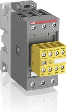
AFS65-30-22-11
 Distributeur Officiel
By ABB
AFS contactors for safety applications
AFS contactors are specifically designed to enhance safety in machine applications. Featuring factory-mounted contact blocks with mechanically linked and mirror contacts, these contactors ensure reliable monitoring and control of circuits. With ABB’s comprehensive safety component range, building protection systems becomes more straightforward and efficient.
Main Benefits:
Safety Compliance: Meets major safety standards (EN ISO 13849 and EN 62061) for secure machinery and equipment use.
Guaranteed Status: Factory-mounted auxiliary contact blocks ensure accurate contactor status monitoring.
Easy Identification: Distinct yellow housing simplifies safety chain recognition.
Streamlined Safety Calculations: Safety values available in FSDT and Sistema tools for easier safety level assessments.
Main Features:
High Power Handling:
Up to 400 kW at 400 V AC-3
Up to 600 hp at 480 V
Up to 1050 A at 690 V AC-1
Up to 900 A for general use
Certified Safety Contacts: Mirror and mechanically linked contacts with third-party certification.
Fast Response: Opening times as low as 20 ms in certain models with PLC interfaces.
Precision Switching: Low-energy auxiliary contacts with a minimum switching capacity of 12 V, 3 mA (10⁻⁷).
Built-in Protection: Integrated surge suppression for enhanced safety.
Dimensions
| Produit Largeur Net | 55 mm |
| Produit Longueur Net | 144 mm |
| Produit Hauteur Net | 125,5 mm |
| Poids net | 1,02 kg |
Technique
| Number of Main Contacts NO | 3 |
| Number of Main Contacts NC | 0 |
| Number of Auxiliary Contacts NO | 2 |
| Number of Auxiliary Contacts NC | 2 |
| Tension | Circuit auxiliaire 690 V, Circuit principal 690 V |
| Fréquence assignée (f) | Circuit auxiliaire 50 / 60 Hz, Circuit principal 50 / 60 Hz |
| Courant thermique conventionnel à l’air libre (Ith) | acc. to IEC 60947-4-1, Open Contactors q = 40 °C 105 A, acc. to IEC 60947-5-1, q = 40 °C 16 A |
| Courant assignée d’emploi AC-1 (Ie) | (690 V) 40 °C 105 A, (690 V) 60 °C 90 A, (690 V) 70 °C 80 A |
| Courant assignée d’emploi AC-3 (Ie) | (415 V) 60 °C 65 A, (440 V) 60 °C 65 A, (500 V) 60 °C 55 A, (690 V) 60 °C 39 A, (380 / 400 V) 60 °C 65 A, (220 / 230 / 240 V) 60 °C 65 A |
| Courant assignée d’emploi AC-3e (Ie) | (415 V) 60 °C 65 A, (440 V) 60 °C 65 A, (500 V) 60 °C 55 A, (690 V) 60 °C 39 A, (380 / 400 V) 60 °C 65 A, (220 / 230 / 240 V) 60 °C 65 A |
| Puissance assignée d’emploi AC-3 (Pe) | (400 V) 30 kW, (415 V) 37 kW, (440 V) 37 kW, (500 V) 37 kW, (690 V) 37 kW, (380 / 400 V) 30 kW, (220 / 230 / 240 V) 18.5 kW |
| Puissance assignée d’emploi AC-3e (Pe) | (415 V) 37 kW, (440 V) 37 kW, (500 V) 37 kW, (690 V) 37 kW, (380 / 400 V) 30 kW, (220 / 230 / 240 V) 18.5 kW |
| Courant assignée d’emploi AC-15 (Ie) | (500 V) 2 A, (690 V) 2 A, (24 / 127 V) 6 A, (220 / 240 V) 4 A, (400 / 440 V) 3 A |
| Courant assigné de courte durée admissible (Icw) | at 40 °C Ambient Temp, in Free Air, from a Cold State 10 s 600 A, at 40 °C Ambient Temp, in Free Air, from a Cold State 15 min 110 A, at 40 °C Ambient Temp, in Free Air, from a Cold State 1 min 250 A, at 40 °C Ambient Temp, in Free Air, from a Cold State 1 s 1000 A, at 40 °C Ambient Temp, in Free Air, from a Cold State 30 s 350 A, for 0.1 s 140 A, for 1 s 100 A |
| Maximum Breaking Capacity | cos phi=0.45 (cos phi=0.35 for Ie > 100 A) at 440 V 950 A, cos phi=0.45 (cos phi=0.35 for Ie > 100 A) at 690 V 600 A |
| Maximum Electrical Switching Frequency | (AC-1) 600 cycles per hour, (AC-15) 1200 cycles per hour, (AC-2 / AC-4) 150 cycles per hour, (AC-3) 1200 cycles per hour, (DC-13) 900 cycles per hour |
| Courant assignée d’emploi DC-13 (Ie) | (24 V) 6 A / 144 W, (48 V) 2.8 A / 134 W, (72 V) 1 A / 72 W, (110 V) 0.55 A / 60 W, (125 V) 0.55 A / 69 W, (220 V) 0.27 A / 60 W, (250 V) 0.27 A / 68 W, (400 V) 0.15 A / 60 W, (500 V) 0.13 A / 65 W, (600 V) 0.1 A / 60 W |
| Tension assignée d’isolement (Ui) | acc. to IEC 60947-4-1 and VDE 0110 (Gr. C) 690 V, acc. to UL/CSA 600 V |
| Tension assignée de tenue aux chocs (Uimp) | 6 kV |
| Maximum Mechanical Switching Frequency | 3600 cycles per hour |
| Rated Control Circuit Voltage (Uc) | 50 Hz 24 ... 60 V, 60 Hz 24 ... 60 V, DC Operation 20 ... 60 V |
| Durée de fonctionnement nominale | Entre la mise hors tension de la bobine et la fermeture du contact NC (normally closed) 19 ... 105 ms, Entre la mise hors tension de la bobine et l'ouverture du contact NO (normally open) 17 ... 100 ms, Entre la mise sous tension de la bobine et l'ouverture du contact NC 38 ... 95 ms, Entre la mise sous tension de la bobine et la fermeture du contact NO 42 ... 100 ms |
| Montage sur rail DIN | TH35-15 (35 x 15 mm Mounting Rail) acc. to IEC 60715, TH35-7.5 (35 x 7.5 mm Mounting Rail) acc. to IEC 60715 |
| Mounting by Screws (not supplied) | 2 x M4 or 2 x M6 screws placed diagonally |
| Connecting Capacity Main Circuit | Flexible with Ferrule 1/2x 4 ... 35 mm², Flexible with Insulated Ferrule 1/2x 4 ... 35 mm², Rigid 1/2x 6 ... 3 5 mm² |
| Connecting Capacity Auxiliary Circuit | Flexible with Ferrule 1/2x 0.75 ... 2.5 mm², Flexible with Insulated Ferrule 2x 0.75 ... 1.5 mm², Flexible with Insulated Ferrule 1x 0.75 ... 2.5 mm², Rigid 1/2x 1 ... 2.5 mm² |
| Connecting Capacity Control Circuit | Flexible with Ferrule 1/2x 0.75 ... 2.5 mm², Flexible with Insulated Ferrule 1x 0.75 ... 2.5 mm², Flexible with Insulated Ferrule 2x 0.75 ... 1.5 mm², Rigid 1/2x 1 ... 2.5 mm² |
| Wire Stripping Length | Auxiliary Circuit 10 mm, Control Circuit 10 mm, Main Circuit 16 mm |
| Indice de protection | acc. to IEC 60529, IEC 60947-1, EN 60529 Auxiliary Terminals IP20, acc. to IEC 60529, IEC 60947-1, EN 60529 Coil Terminals IP20, acc. to IEC 60529, IEC 60947-1, EN 60529 Main Terminals IP10 |
| Type de borne | Bornes à vis |
Technique UL/CSA
| General Use Rating UL/CSA | (600 V AC) 90 A |
| Puissance nominale UL/CSA | (120 V AC) Single Phase 5 hp, (200 ... 208 V AC) Three Phase 20 hp, (220 ... 240 V AC) Three Phase 25 hp, (240 V AC) Single Phase 15 hp, (440 ... 480 V AC) Three Phase 50 hp, (550 ... 600 V AC) Three Phase 60 hp |
| Tightening Torque UL/CSA | Auxiliary Circuit 11 in·lb, Control Circuit 11 in·lb, Main Circuit 35 in·lb |
Environnement
| Température de l’air ambiant | Close to Contactor Fitted with Thermal O/L Relay -40 ... 70 °C, Close to Contactor without Thermal O/L Relay -40 ... 70 °C, Close to Contactor for Storage -60 ... +80 °C |
| Climatic Withstand | Category B according to IEC 60947-1 Annex Q |
| Altitude de fonctionnement maximale autorisée | Without Derating 3000 m |
| Resistance to Vibrations acc. to IEC 60068-2-6 | 5 ... 300 Hz 3 g closed position / 3 g open position |
| Résistance aux chocs selon CEI 60068-2-27 | Closed, Shock Direction: A 25 g, Closed, Shock Direction: B1 25 g, Closed, Shock Direction: B2 15 g, Closed, Shock Direction: C1 25 g, Closed, Shock Direction: C2 25 g |
| Statut RoHS | Following EU Directive 2011/65/EU |
Pourquoi Proax pour ABB AFS65-30-22-11?
Proax est un distributeur autorisé de ABB AFS65-30-22-11 et l'un des plus grands distributeurs de ABB en Amérique du Nord. Notre équipe technique interne, qui est hautement qualifiée, est prête à répondre à vos besoins techniques!
Avez-vous une question? pour vous aider à obtenir le bon produit le plus rapidement possible pour votre projet. Nous sommes toujours là pour vous aider!
| Autres noms | AFS65302211 |
| Taille de l'emballage | 1 |
 The AFS65-30-22-13 is a 3 pole - 690 V IEC or 600 V UL contactor with fixed 2 N.O + 2 N.C. front mounted auxiliary contact blocks with screw connections, controlling motors up to 30 kW / 400 V AC (AC-3) or 50 hp / 480 V UL and switching power circuits up to 105 A (AC-1) or 90 A UL general use. AFS contactors can be easily integrated in machine manufacturer’s systems complying with main standards EN ISO 13849 and EN 62061 - guaranteeing the safe use of your machinery and equipment. An easily identifiable yellow low energy auxiliary contact block ensures the status feedback circuits required in machine safety applications. Thanks to the AF technology, the contactor has a wide control voltage range (100 ... 250 V), managing large control voltage variations, reducing panel energy consumptions and ensuring distinct operations in unstable networks. Furthermore, surge protection is built-in, offering a compact solution. AF contactors have a block type design, can be easily extended with add-on auxiliary contact blocks and an additional wide range of accessories.