


1159042
SKU
PHX1159042
MPN
TRIO3-PS/3AC/24DC/10
Weight
0.764 kg
Series TRIO3-PS
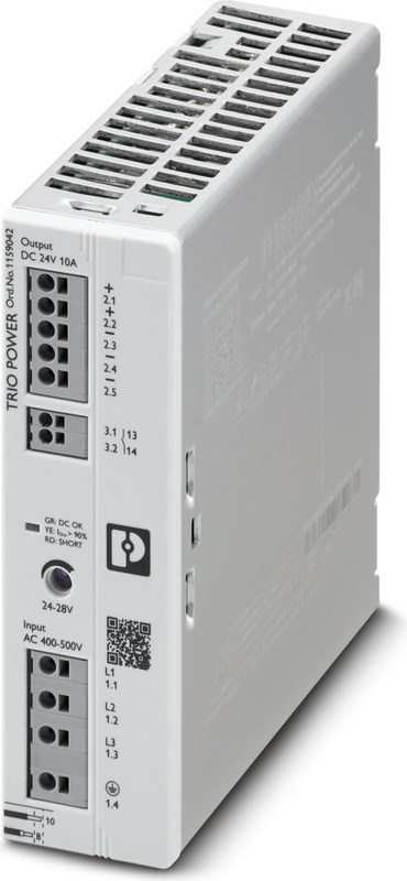
TRIO3-PS/3AC/24DC/10 - Power supply unit
Primary-switched power supply unit, TRIO POWER, Push-in connection, DIN rail mounting, input: 3-phase, output: 24 V DC / 10 A, adjustable from 24 V DC ... 28 V DC
- Space-saving due to its low overall width and capability of being mounted side by side
- Robust and reliable due to dynamic boost with a powerful output characteristic curve
- Easy handling with Push-in connection technology
- Smart diagnostics with multicolor LEDs and collective relay contact for a clear status display, with optional IO-Link
- High system availability: power reliability in one device due to the integrated compact multi-channel circuit breaker
Documents
Technical Specifications
AC operation
| Supply system configuration | Star network (TN, TT, IT (PE)) |
| Nominal input voltage range | 3x 400 V AC ... 500 V AC |
| Input voltage range | 3x 400 V AC ... 500 V AC -20 % ... +10 % |
| Input voltage range | 2x 400 V AC ... 500 V AC ±10 % |
| Typical national grid voltage | 3x 400 V AC |
| Typical national grid voltage | 3x 480 V AC |
| Voltage type of supply voltage | AC |
| Inrush Current | < 13 A (25 °C) |
| Inrush current integral (I2t) | < 0.25 A2s |
| Frequency range (fN) | 50 Hz ... 60 Hz ±10 % |
| Mains buffering time | typ. 35 ms (3x 400 V AC) |
| Mains buffering time | typ. 58 ms (3x 480 V AC) |
| Current consumption | 3x 0.68 A (3x 400 V AC) |
| Current consumption | 3x 0.57 A (3x 500 V AC) |
| Current consumption | 2x 1.3 A (2x 400 V AC) |
| Current consumption | 2x 1.1 A (2x 500 V AC) |
| Protective circuit | Transient protection; Varistor |
| Power factor (cos phi) | 0.57 (3x 480 V AC) |
| Device mains fuse | 3.15 A internal (device protection) |
| Recommended breaker for input protection | 3x 3 A ... 16 A (Characteristic B, C, D, K or comparable) |
| Discharge current to PE | < 3.5 mA |
Output data
| Efficiency | typ. 92.3 % (3x 400 V AC) |
| Efficiency | typ. 92.4 % (3x 480 V AC) |
| Nominal Output Voltage | 24 V DC |
| Setting range of the output voltage (USet) | 24 V DC ... 28 V DC (> 24 V DC, constant capacity restricted) |
| Nominal output current (IN) | 10 A |
| Dynamic Boost (IDyn.Boost) | max. 15 A (5 s) |
| Short-circuit-proof | yes |
| No-load proof | yes |
| Derating | 60 °C ... 70 °C |
| Crest factor | typ. 2.77 (3x 400 V AC) |
| Crest factor | typ. 2.94 (3x 480 V AC) |
| Output power (PN) | 240 W |
| Output power (PDyn. Boost) | max. 360 W (5 s) |
| Connection in parallel | yes, for increasing power and redundancy with diode |
| Connection in series | yes, for increased output voltage (observe SELV limit) |
| Feedback voltage resistance | ≤ 35 V DC |
| Protection against overvoltage at the output (OVP) | ≤ 35 V DC |
| Residual ripple | typ. 10 mVPP (with nominal values) |
| Control deviation | < 1 % (change in load, static 10 % ... 90 %) |
| Control deviation | < 3 % (change in load, dynamic 10 % ... 90 %) |
| Control deviation | < 0.1 % (change in input voltage ±10 %) |
| Rise time | ≤ 1 s (UOut = 10 % ... 90 %) |
| Minimum no-load power dissipation | < 1.16 W (3x 400 V AC) |
| Maximum no-load power dissipation | < 1.58 W (3x 480 V AC) |
| Minimum nominal load power dissipation | < 19.93 W (3x 400 V AC) |
| Power loss nominal load max. | < 20.18 W (3x 480 V AC) |
| Integrated fuse protection | no |
Input
| Position | 1.x |
Connection technology
| Position marking | 1.1 (L1), 1.2 (L2), 1.3 (L3), 1.4 () |
Conductor connection
| Connection Method | Push-in connection |
| rigid | 0.2 mm² ... 4 mm² |
| rigid | 1.5 mm² (recommended) |
| flexible | 0.2 mm² ... 2.5 mm² |
| flexible | 1.5 mm² (recommended) |
| flexible with ferrule without plastic sleeve | 0.25 mm² ... 2.5 mm² |
| flexible with ferrule without plastic sleeve | 1.5 mm² (recommended) |
| flexible with ferrule with plastic sleeve | 0.25 mm² ... 2.5 mm² |
| flexible with ferrule with plastic sleeve | 1.5 mm² (recommended) |
| AWG | 24 ... 12 (Cu) |
| AWG | 16 (recommended) |
| Stripping length | 10 mm (Rigid/flexible/ferrule) |
Output
| Position | 2.x |
Connection technology
| Position marking | 2.1, 2.2 (+), 2.3, 2.4, 2.5 (-) |
Conductor connection
| Connection Method | Push-in connection |
| rigid | 0.2 mm² ... 4 mm² |
| rigid | 1.5 mm² (recommended) |
| flexible | 0.2 mm² ... 2.5 mm² |
| flexible | 2.5 mm² (recommended) |
| flexible with ferrule without plastic sleeve | 0.25 mm² ... 2.5 mm² (Cu) |
| flexible with ferrule without plastic sleeve | 2.5 mm² (recommended) |
| flexible with ferrule with plastic sleeve | 0.25 mm² ... 2.5 mm² |
| flexible with ferrule with plastic sleeve | 1.5 mm² (recommended) |
| AWG | 24 ... 12 (Cu) |
| AWG | 16 (recommended) |
| Stripping length | 10 mm (Rigid/flexible/ferrule) |
Signal
| Position | 3.x |
Connection technology
| Position marking | 3.1 (13), 3.2 (14) |
Conductor connection
| Connection Method | Push-in connection |
| rigid | 0.2 mm² ... 1.5 mm² |
| rigid | 0.5 mm² (recommended) |
| flexible | 0.2 mm² ... 1.5 mm² |
| flexible | 0.5 mm² (recommended) |
| flexible with ferrule without plastic sleeve | 0.25 mm² ... 1.5 mm² (Cu) |
| flexible with ferrule without plastic sleeve | 0.5 mm² (recommended) |
| flexible with ferrule with plastic sleeve | 0.25 mm² ... 0.75 mm² |
| flexible with ferrule with plastic sleeve | 0.5 mm² (recommended) |
| AWG | 24 ... 16 (Cu) |
| AWG | 20 (recommended) |
| Stripping length | 10 mm (Rigid/flexible/ferrule) |
LED signaling
| Types of signaling | LED DC OK – signal state operation (UN = 24 V DC, IOut = IN) |
| Function | Visual operating state display |
| Color | red, yellow, green (multicolor LED) |
| LED off | Supply voltage input AC not present (Off) |
| LED on (green), DC OK | UOut > 21 V DC and IOut < 0.9 x IN (On (green), DC OK) |
| LED on (yellow), IOut > 90% | UOut > 21 V DC and IOut > 0.9 x IN (On (yellow), IOut > 90% ) |
| LED on (red), ISHORT | UOut < 21 V DC and IOut > 0.9 x IN (On (red), ISHORT) |
| LED on (flashing red) OVP | UOUT > OVP (Over voltage protection) (On (flashing red)) |
Signal output DC OK
| Position | 3.x |
| Type of signaling | DC OK switch contact - signal state operation (UN = 24 V DC, IOut = IN) |
| Position marking | 3.1 (13), 3.2 (14) |
| Function | Operating state forwarding |
| Switch contact (floating) | OptoMOS |
| Switching voltage | max. 30 V DC (SELV) |
| Current carrying capacity | max. 100 mA |
| State condition | UOut > 21 V DC and IOut < 0.9 x IN (Contact closed) |
| State condition | UOut < 21 V DC or IOut > 0.9 x IN (averaging over 60 s) (Contact open) |
Electrical properties
| Number of phases | 3.00 |
| Insulation voltage input/output | 6 kV DC (type test) |
| Insulation voltage input/output | 3.1 kV DC (routine test) |
Product properties
| Product family | TRIO POWER |
| MTBF (IEC 61709, SN 29500) | > 1400000 h (25 °C) |
| MTBF (IEC 61709, SN 29500) | > 820000 h (40 °C) |
| MTBF (IEC 61709, SN 29500) | > 320000 h (60 °C) |
| Environmental protection directive | RoHS Directive 2011/65/EU |
| Environmental protection directive | WEEE |
| Environmental protection directive | Reach |
Insulation characteristics
| Protection class | I |
| Degree of pollution | 2 |
Item dimensions
| Width | 40 mm |
| Height | 135 mm |
| Depth | 132 mm |
| Depth | 125 mm (Device depth (DIN rail mounting)) |
Installation dimensions
| Installation distance right/left | 0 mm / 0 mm |
| Installation distance top/bottom | 50 mm / 50 mm |
Mounting
| Mounting Type | DIN rail mounting |
| Assembly note | alignable: 0 mm horizontally, 30 mm vertically |
| Mounting Position | horizontal DIN rail NS 35, EN 60715 |
| With protective coating | no |
Material specifications
| Flammability rating according to UL 94 | V0 (Housing, terminal blocks) |
| Hood version | Polycarbonate |
| Side element version | Aluminum |
Ambient conditions
| Degree of Protection | IP20 |
| Ambient Temperature (Operation) | -25 °C ... 70 °C (> 60 °C Derating: 2,5 %/K) |
| Ambient temperature (storage/transport) | -40 °C ... 85 °C |
| Ambient temperature (start-up type tested) | -40 °C |
| Maximum altitude | ≤ 5000 m (> 2000 m, Derating: 10 %/1000 m) |
| Max. permissible relative humidity (operation) | ≤ 95 % (at 25 °C, non-condensing) |
| Shock (operation) | 18 ms, 30g, per spatial direction (IEC 60068-2-27) |
| Vibration (Operation) | 10 Hz ... 50 Hz, amplitude ±0.2 mm (IEC 60068-2-6) |
| Vibration (Operation) | 50 Hz ... 150 Hz, 2.3g, 90 min. |
| Temp code | T4 (-25 ... +70 °C; > 60 °C, Derating: 2,5 %/K) |
Overvoltage category
| EN 61010-1 | III (≤ 2000 m) |
| EN 61010-1 | II (≤ 5000 m) |
| EN 61010-2-201 | III (≤ 2000 m) |
| EN 61010-2-201 | II (≤ 5000 m) |
Safety of power supply units up to 1100 V (insulation distances)
| Standard designation | Safety of power supply units up to 1100 V (insulation distances) |
| Standards/specifications | DIN EN 61558-2-16 |
Electrical safety
| Standard designation | Electrical safety |
| Standards/specifications | IEC 61010-2-201 (SELV) |
Safety for measurement, control, and laboratory equipment
| Standard designation | Safety for equipment for measurement, control, and laboratory use |
| Standards/specifications | IEC 61010-1 |
Protective extra-low voltage
| Standard designation | Protective extra-low voltage |
| Standards/specifications | IEC 61010-1 (SELV) |
| Standards/specifications | IEC 61010-2-201 (PELV) |
Safe isolation
| Standard designation | Safe isolation |
| Standards/specifications | IEC 61558-2-16 |
| Standards/specifications | IEC 61010-2-201 |
Limitation of harmonic line currents
| Standard designation | Limitation of harmonic line currents |
| Standards/specifications | EN 61000-3-2 |
Mains variation/undervoltage
| Standard designation | Mains variation/undervoltage |
| Standards/specifications | SEMI F47 |
| Standards/specifications | EN 61000-4-11 |
UL
| Identification | UL/C-UL Listed UL 61010-1 |
| Identification | UL/C-UL Listed UL 61010-2-201 |
ANSI/UL 121201
| Identification | PROCESS CONTROL EQUIPEMENT FOR HAZARDOUS LOCATIONS |
| Identification | (EN) This equipment is suitable for use in Class I, Division 2, Groups A, B, C and D, Hazardous Locations, or non-hazardous locations only.(FR) Cet appareil convient uniquement pour une utilisation en atmosphères explosibles de classe I, division 2, groupes A, B, C et D ou en atmosphères non explosibles. |
| Identification | (EN) WARNING: Explosion Hazard - Do not connect or disconnect equipment unless power has been switched off or the area is known to be non-hazardous.(FR) AVERTISSEMENT : risque d'explosion - ne pas connecter ou déconnecter les équipements sauf si l'alimentation a été coupée ou si la zone est réputée non dangereuse. |
| Identification | (EN) If the equipment is used in a manner not specified by the manufacturer, the protection provided by the equipment may be impaired.(FR) Si l'équipement est utilisé d'une manière non spécifiée par le fabricant, la protection fournie par cet équipement peut être altérée. |
| Identification | (EN) This equipement must be installed in a suitable, tool secured/key locked enclosure.(FR) Cet équipement doit être installé dans un boîtier approprié, verrouillé par une clé ou dont l'ouverture nécessite l'utilisation d'un outil. |
EMC data
| Electromagnetic compatibility | Conformance with EMC Directive 2014/30/EU |
| Low Voltage Directive | Conformance with Low Voltage Directive 2014/35/EC |
| Interference emission | Interference emission in accordance with EN 61000-6-3 (residential and commercial) and EN 61000-6-4 (industrial) |
| Noise immunity | Immunity in accordance with EN 61000-6-1 (residential), EN 61000-6-2 (industrial) |
| Conducted noise emission | EN 55016 |
| Conducted noise emission | EN 61000-6-3 (Class B) |
| Noise emission | EN 55016 |
| Noise emission | EN 61000-6-3 (Class B) |
Harmonic currents
| Standards/regulations | EN 61000-3-2 |
| Standards/regulations | EN 61000-3-2 (Class A) |
| Frequency Range | 0 kHz ... 2 kHz |
Flicker
| Standards/regulations | EN 61000-3-3 |
| Standards/regulations | EN 61000-3-3 |
| Frequency Range | 0 kHz ... 2 kHz |
Electrostatic discharge
| Standards/regulations | EN 61000-4-2 |
| Contact discharge | 6 kV (Test Level 3) |
| Discharge in air | 8 kV (Test Level 3) |
| Comments | Criterion B |
Electromagnetic HF field
| Standards/regulations | EN 61000-4-3 |
| Frequency Range | 80 MHz ... 1 GHz |
| Test field strength | 10 V/m (Test Level 3) |
| Frequency Range | 1 GHz ... 6 GHz |
| Test field strength | 10 V/m (Test Level 3) |
| Comments | Criterion A |
Fast transients (burst)
| Standards/regulations | EN 61000-4-4 |
| Input | asymmetrical 2 kV (Test Level 3) |
| Output | asymmetrical 2 kV (Test Level 3) |
| Signal | asymmetrical 1 kV (Test Level 3) |
| Comments | Criterion A |
Surge voltage load (surge)
| Standards/regulations | EN 61000-4-5 |
| Input | symmetrical 1 kV (Test Level 3) |
| Input | asymmetrical 2 kV (Test Level 3) |
| Output | symmetrical 0.5 kV (Test Level 2) |
| Output | asymmetrical 1 kV (Test Level 2) |
| Signal | asymmetrical 1 kV (Test Level 2) |
| Comments | Criterion B |
Conducted interference
| Standards/regulations | EN 61000-4-6 |
| I/O/S | asymmetrical |
| Frequency Range | 0.15 MHz ... 80 MHz |
| Comments | Criterion A |
| Voltage | 10 V (Test Level 3) |
Voltage dips
| Standards/regulations | EN 61000-4-11 |
| Voltage | 400 V AC |
| Frequency | 50 Hz |
| Voltage dip | 70 % |
| Number of periods | 25 periods |
| Additional text | Class 3 |
| Comments | Criterion A |
| Voltage dip | 40 % |
| Number of periods | 10 periods |
| Additional text | Class 3 |
| Comments | Criterion A |
| Voltage dip | 0 % |
| Number of periods | 1 period |
| Additional text | Class 3 |
| Comments | Criterion A |
Criteria
| Criterion A | Normal operating behavior within the specified limits. |
| Criterion B | Temporary impairment to operational behavior that is corrected by the device itself. |
| Criterion C | Temporary adverse effects on the operating behavior, which the device corrects automatically or which can be restored by actuating the operating elements. |
Why Proax for Phoenix Contact 1159042?
Proax is an authorized distributor of Phoenix Contact 1159042 and one of Phoenix Contact's largest distributors in North America. Our highly skilled in-house technical team is ready to assist with any technical needs.
Have a question in mind? to help you get the right product as quickly as possible for your project. We're always here to help!
Short Lead Time
Highly Trained Staff
Live Chat
Technical Support
Local Inventory
60+ Years Experience
Additional Information
| Pack Size | 1 |
Recommended

 Primary-switched power supply unit, TRIO POWER, Push-in connection, DIN rail mounting, input: 3-phase, output: 24 V DC / 20 A, adjustable from 24 V DC ... 28 V DC
 Primary-switched power supply unit, TRIO POWER, Push-in connection, DIN rail mounting, input: 3-phase, output: 24 V DC / 40 A, adjustable from 24 V DC ... 28 V DC
 Primary-switched power supply unit, TRIO POWER, Push-in connection, 8-channel electronic circuit breaker, IO-Link, DIN rail mounting, input: 3-phase, output: 24 V DC / 40 A, adjustable from 24 V DC ... 28 V DC
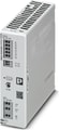 Primary-switched power supply unit, TRIO POWER, Push-in connection, DIN rail mounting, input: 1-phase, output: 24 V DC / 10 A, adjustable from 24 V DC ... 28 V DC
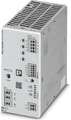 Primary-switched power supply unit, TRIO POWER, Push-in connection, 4-channel electronic circuit breaker, IO-Link, DIN rail mounting, input: 1-phase, output: 24 V DC / 10 A, adjustable from 24 V DC ... 28 V DC
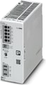 Primary-switched power supply unit, TRIO POWER, Push-in connection, DIN rail mounting, input: 1-phase, output: 24 V DC / 20 A, adjustable from 24 V DC ... 28 V DC
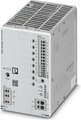 Primary-switched power supply unit, TRIO POWER, Push-in connection, 8-channel electronic circuit breaker, IO-Link, DIN rail mounting, input: 1-phase, output: 24 V DC / 20 A, adjustable from 24 V DC ... 28 V DC
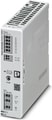 Primary-switched power supply unit, TRIO POWER, Push-in connection, DIN rail mounting, input: 1-phase, output: 24 V DC / 5 A, adjustable from 24 V DC ... 28 V DC