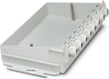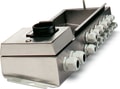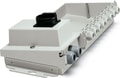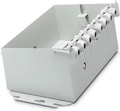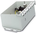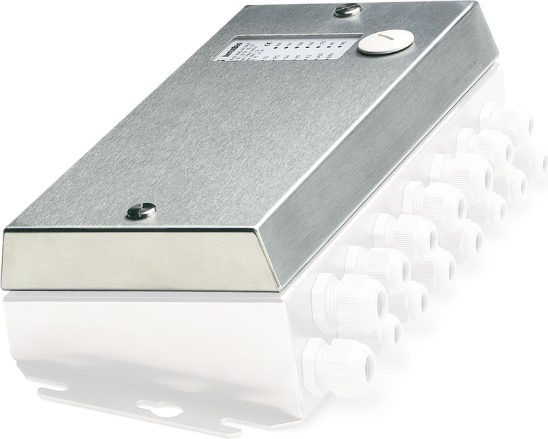
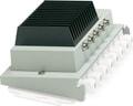
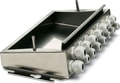
The figure shows version IBS IP 400 ME-ELR R-3A DI4F
2732965
SKU
PHX2732965
MPN
IBS IP 400 ME-MLR 2-8A DI4F
Weight
2.308 kg
This product is Not Cancellable/Not Returnable
Series IBS-IP
IBS IP 400 ME-MLR 2-8A DI4F - Motor starter
Electromechanical motor starter, electronic module without lower part of housing, 2-channel direct starter
Technical Specifications
Utilization restriction
| EMC note | EMC: class A product, see manufacturer's declaration in the download area |
Product properties
| Type | Stand-Alone |
| Type | Electromechanical motor starter |
| Diagnostics messages | Mains failure, phase failure Error message in the diagnostic code (bus) and display via the LED ERR on the module |
| Diagnostics messages | Motor connector not plugged in, motor temperature exceeded, thermistor line short-circuited Error message in the diagnostic code (bus) and display via the LED ERR on the module |
| Diagnostics messages | Sensor supply failure Error message in the diagnostic code (bus) and display via the LED ERR on the module |
| Diagnostics messages | Overcurrent Error message in the diagnostic code (bus) and display via the LED ERR on the module |
| Diagnostics messages | Output stage cannot be controlled Error message in the diagnostic code (bus) and display via the LED ERR on the module |
| Diagnostics messages | Module error during self test Message to the master |
Supply: Module electronics
| Connection Method | POWER-COMBICON |
| Designation | Terminal strip X13 and X15 |
| Number of Positions | 2 |
| Pg screw connection | Pg11 |
| Supply Voltage | 24 V DC (US1 / US2) |
| Supply Voltage Range | 20 V DC ... 30 V DC (including ripple) |
| Supply current | typ. 0.11 A (at US1 = 24 V; plus current of digital inputs/outputs) |
| Ripple | Permissible ripple 3.6 Vpp within the permissible voltage range |
| Max. current carrying capacity | 16 A |
| Derating | Above 30°C: 0.1 A/ K (at 4 mm²), above 30°C: 0.3 A/ K (at 1.5 mm²) |
Electrical isolation/isolation of the voltage ranges
| Test voltage: Incoming/outgoing remote bus | 350 V AC, 50 Hz, 1 min. |
| Test voltage: Remote bus / supply voltage US1 | 350 V AC, 50 Hz, 1 min. |
| Test voltage: Between supply voltages | 350 V AC, 50 Hz, 1 min. |
Digital: Digital inputs
| Number of Inputs | 4 |
| Connection Method | MINI COMBICON |
| Connection technology | 3-, 4-conductor |
| Number of Positions | 10 |
| Input Voltage | 24 V DC (US1) |
| Input voltage range "0" signal | -30 V ... 5 V (binary "0") |
| Input voltage range "1" signal | 13 V ... 30 V (binary "1") |
| Filter time | 3 ms |
| Typical input current per channel | approx. 5 mA (for US1 = 24 V) |
INTERBUS
| Connection Method | MINI COMBICON |
| Designation connection point | X30 (IN) and X31 (OUT) |
| Number of Positions | 10 |
| Permissible conductor cross section | max. 1.5 mm² |
Diagnostic messages
| Diagnostics | Mains failure, phase failure |
| Message | Error message in the diagnostic code (bus) and display via the LED ERR on the module |
| Diagnostics | Motor connector not plugged in, motor temperature exceeded, thermistor line short-circuited |
| Message | Error message in the diagnostic code (bus) and display via the LED ERR on the module |
| Diagnostics | Sensor supply failure |
| Message | Error message in the diagnostic code (bus) and display via the LED ERR on the module |
| Diagnostics | Overcurrent |
| Message | Error message in the diagnostic code (bus) and display via the LED ERR on the module |
| Diagnostics | Output stage cannot be controlled |
| Message | Error message in the diagnostic code (bus) and display via the LED ERR on the module |
| Diagnostics | Module error during self test |
| Message | Message to the master |
Dimensions
| Width | 384 mm |
| Height | 182 mm |
| Depth | 100 mm |
| Drill hole spacing | 360 mm |
| Note on dimensions | Module electronics without lower part |
Technical data
| Drill hole spacing | 360 mm |
Ambient conditions
| Degree of Protection | IP67 |
| Ambient Temperature (Operation) | -20 °C ... 55 °C (non-condensing) |
| Note | Notes on operation Line protection for the network supply line, max. 20 A. Observe derating of the POWER-COMBICON connector |
| Note | Notes on operation Permitted network type TN network, TT network, IT network available on request |
| Air pressure (operation) | 86 kPa ... 106 kPa (up to 2000 m above sea level) |
| Air pressure (storage/transport) | 86 kPa ... 106 kPa (up to 2000 m above sea level) |
| Ambient temperature (storage/transport) | -25 °C ... 75 °C |
| Permissible humidity (operation) | 4 % ... 100 % (non-condensing) |
| Permissible humidity (storage/transport) | 75 % (slight temporary condensation may sometimes appear on the housing) |
Standards and Regulations
| Protection class | I (IEC 61140, EN 61140, VDE 0140-1) |
| Noise emission | Test of emitted interference, housing, in acc. with EN 50081-2:1993 EN 55011:1991 class A |
Air clearances and creepage distances
| Air clearances and creepage distances | in accordance with EN 50178: 1998 |
Mounting
| Mounting Type | Wall mounting |
Why Proax for Phoenix Contact 2732965?
Proax is an authorized distributor of Phoenix Contact 2732965 and one of Phoenix Contact's largest distributors in North America. Our highly skilled in-house technical team is ready to assist with any technical needs.
Have a question in mind? to help you get the right product as quickly as possible for your project. We're always here to help!
Short Lead Time
Highly Trained Staff
Live Chat
Technical Support
Local Inventory
60+ Years Experience
Additional Information
| Pack Size | 1 |
Recommended

 IBS IP 400 ME-MLR R-8A DI4F - Electromechanical motor starter, electronic module without lower part of housing, 1-channel reversing starter
 IBS IP 400 ME-ELR 2-3A DI4 - Electronic motor starter, electronic module without lower part of housing, 2-channel direct starter
- IBS IP 400 ME-ELR 2-3A FO - Electronic motor starter, fiber optic connection, electronic module without lower part of housing, 2-channel direct starter, 4 digital inputs and 2 digital outputs, sheet steel housing, IP54 protection
- IBS IP 400 ME-ELR 1-3A DI4 - Electronic motor starter, electronic module without lower part of housing, 1-channel direct starter
- IBS IP 400 ME-ELR R-3A DI4 - Electronic motor starter, electronic module without lower part of housing, 1-channel reversing starter
- IBS IP 400 ME-ELR R-3A FO - Electronic motor starter, fiber optic connection, electronic module without lower part of housing, 1-channel reversing starter, 4 digital inputs and 2 digital outputs, sheet steel housing, IP54 protection
 IBS IP 400 ME-VFD 1-3A DI4 - Variable frequency drive, 4 digital inputs, IP54 protection, for connecting an asynchronous motor, without lower part of the housing
 IBS IP 400 ME-VFD 1-3A DI4F - 1-channel variable frequency drive, with 4 digital inputs, sheet steel housing, electronic module without lower part of housing, IP65/67 protection
- IBS IP 400 ME-VFD 3A FO - 1-channel variable frequency drive, 4 digital inputs and 2 digital outputs. Sheet steel housing, degree of protection: IP54, fiber optic connection
 IBS IP 400 MBH -F - Lower part of the housing, high-grade steel version, degree of protection: IP67
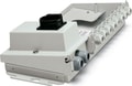 IBS IP 400 FO-MBH/MS - Lower housing part with integrated maintenance switch, IP54 protection, fuse holder, fiber optic guide plate, power distribution and jumpering for 24 V (U S1 and U S2)
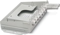 IBS IP 400 FO-MBH - Lower housing part, sheet steel, IP54 protection, fiber optic guide plate, jumpering for 24 V (U S1 and U S2)