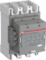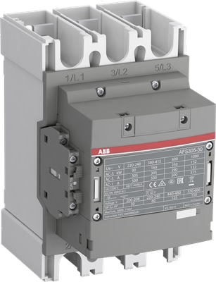
AFS305-30-12-13
By ABB
AFS contactors for safety applications
AFS contactors are specifically designed to enhance safety in machine applications. Featuring factory-mounted contact blocks with mechanically linked and mirror contacts, these contactors ensure reliable monitoring and control of circuits. With ABB’s comprehensive safety component range, building protection systems becomes more straightforward and efficient.
Main Benefits:
Safety Compliance: Meets major safety standards (EN ISO 13849 and EN 62061) for secure machinery and equipment use.
Guaranteed Status: Factory-mounted auxiliary contact blocks ensure accurate contactor status monitoring.
Easy Identification: Distinct yellow housing simplifies safety chain recognition.
Streamlined Safety Calculations: Safety values available in FSDT and Sistema tools for easier safety level assessments.
Main Features:
High Power Handling:
Up to 400 kW at 400 V AC-3
Up to 600 hp at 480 V
Up to 1050 A at 690 V AC-1
Up to 900 A for general use
Certified Safety Contacts: Mirror and mechanically linked contacts with third-party certification.
Fast Response: Opening times as low as 20 ms in certain models with PLC interfaces.
Precision Switching: Low-energy auxiliary contacts with a minimum switching capacity of 12 V, 3 mA (10⁻⁷).
Built-in Protection: Integrated surge suppression for enhanced safety.
Dimensions
| Product Net Width | 140 mm |
| Product Net Depth / Length | 180 mm |
| Product Net Height | 225 mm |
| Product Net Weight | 4 kg |
Technical
| Number of Main Contacts NO | 3 |
| Number of Main Contacts NC | 0 |
| Number of Auxiliary Contacts NO | 1 |
| Number of Auxiliary Contacts NC | 2 |
| Number of Poles | 3P |
| Rated Operational Voltage | Main Circuit 1000 V |
| Rated Frequency (f) | Main Circuit 50 / 60 Hz |
| Conventional Free-air Thermal Current (Ith) | acc. to IEC 60947-4-1, Open Contactors Θ = 40 °C 500 A |
| Rated Operational Current AC-1 (Ie) | (1000 V) 40 °C 375 A |
| Rated Operational Current AC-1 (Ie) | (1000 V) 60 °C 325 A |
| Rated Operational Current AC-1 (Ie) | (1000 V) 70 °C 260 A |
| Rated Operational Current AC-1 (Ie) | (690 V) 40 °C 500 A |
| Rated Operational Current AC-1 (Ie) | (690 V) 60 °C 400 A |
| Rated Operational Current AC-1 (Ie) | (690 V) 70 °C 325 A |
| Rated Operational Current AC-3 (Ie) | (415 V) 60 °C 305 A |
| Rated Operational Current AC-3 (Ie) | (440 V) 60 °C 305 A |
| Rated Operational Current AC-3 (Ie) | (500 V) 60 °C 290 A |
| Rated Operational Current AC-3 (Ie) | (690 V) 60 °C 290 A |
| Rated Operational Current AC-3 (Ie) | (1000 V) 60 °C 131 A |
| Rated Operational Current AC-3 (Ie) | (380 / 400 V) 60 °C 305 A |
| Rated Operational Current AC-3 (Ie) | (220 / 230 / 240 V) 60 °C 305 A |
| Rated Operational Current DC-1 (Ie) | (110 V) 1-Pole, 40 °C 500 A |
| Rated Operational Current DC-1 (Ie) | (220 V) 2 Poles in Series, 40 °C 500 A |
| Rated Operational Current DC-1 (Ie) | (220 V) 3 Poles in Series, 40 °C 500 A |
| Rated Operational Current DC-3 (Ie) | (110 V) 1-Pole, 40 °C 400 A |
| Rated Operational Current DC-3 (Ie) | (220 V) 2 Poles in Series, 40 °C 400 A |
| Rated Operational Current DC-3 (Ie) | (220 V) 3 Poles in Series, 40 °C 400 A |
| Rated Operational Current DC-5 (Ie) | (110 V) 1-Pole, 40 °C 400 A |
| Rated Operational Current DC-5 (Ie) | (220 V) 2 Poles in Series, 40 °C 400 A |
| Rated Operational Current DC-5 (Ie) | (220 V) 3 Poles in Series, 40 °C 400 A |
| Rated Operational Power AC-3 (Pe) | (415 V) 160 kW |
| Rated Operational Power AC-3 (Pe) | (440 V) 160 kW |
| Rated Operational Power AC-3 (Pe) | (500 V) 200 kW |
| Rated Operational Power AC-3 (Pe) | (690 V) 250 kW |
| Rated Operational Power AC-3 (Pe) | (1000 V) 185 kW |
| Rated Operational Power AC-3 (Pe) | (380 / 400 V) 160 kW |
| Rated Operational Power AC-3 (Pe) | (220 / 230 / 240 V) 90 kW |
| Rated Breaking Capacity AC-3 | 8 x Ie AC-3 |
| Rated Making Capacity AC-3 | 10 x Ie AC-3 |
| Short-Circuit Protective Devices | gG Type Fuses 500 A |
| Rated Short-time Withstand Current Low Voltage (Icw) | at 40 °C Ambient Temp, in Free Air, from a Cold State 10 s 2440 A |
| Rated Short-time Withstand Current Low Voltage (Icw) | at 40 °C Ambient Temp, in Free Air, from a Cold State 15 min 500 A |
| Rated Short-time Withstand Current Low Voltage (Icw) | at 40 °C Ambient Temp, in Free Air, from a Cold State 1 min 996 A |
| Rated Short-time Withstand Current Low Voltage (Icw) | at 40 °C Ambient Temp, in Free Air, from a Cold State 1 s 3050 A |
| Rated Short-time Withstand Current Low Voltage (Icw) | at 40 °C Ambient Temp, in Free Air, from a Cold State 30 s 1409 A |
| Maximum Breaking Capacity | cos phi=0.45 (cos phi=0.35 for Ie > 100 A) at 440 V 4600 A |
| Maximum Breaking Capacity | cos phi=0.45 (cos phi=0.35 for Ie > 100 A) at 690 V 3800 A |
| Rated Insulation Voltage (Ui) | acc. to IEC 60947-4-1 and VDE 0110 (Gr. C) 1000 V |
| Rated Insulation Voltage (Ui) | acc. to UL/CSA 600 V |
| Rated Impulse Withstand Voltage (Uimp) | Main Circuit 8 kV |
| Maximum Electrical Switching Frequency | (AC-1) 300 cycles per hour |
| Maximum Electrical Switching Frequency | (AC-2 / AC-4) 150 cycles per hour |
| Maximum Electrical Switching Frequency | (AC-3) 300 cycles per hour |
| Mechanical Durability | 5 million |
| Maximum Mechanical Switching Frequency | 300 cycles per hour |
| Coil Operating Limits | (acc. to IEC 60947-4-1) 0.85 x Uc Min. ... 1.1 x Uc Max. (at θ ≤ 70 °C) |
| Rated Control Circuit Voltage (Uc) | 50 Hz 100 ... 250 V |
| Rated Control Circuit Voltage (Uc) | 60 Hz 100 ... 250 V |
| Rated Control Circuit Voltage (Uc) | DC Operation 100 ... 250 V |
| Coil Consumption | Holding at Max. Rated Control Circuit Voltage 50 Hz 17.5 V·A |
| Coil Consumption | Holding at Max. Rated Control Circuit Voltage 60 Hz 17.5 V·A |
| Coil Consumption | Holding at Max. Rated Control Circuit Voltage DC 3 W |
| Coil Consumption | Pull-in at Max. Rated Control Circuit Voltage 50 Hz 385 V·A |
| Coil Consumption | Pull-in at Max. Rated Control Circuit Voltage 60 Hz 385 V·A |
| Coil Consumption | Pull-in at Max. Rated Control Circuit Voltage DC 410 W |
| Power Loss | at Rated Operating Conditions per Pole 19 W |
| Operate Time | Between Coil De-energization and NO Contact Opening 37 ... 47 ms |
| Operate Time | Between Coil Energization and NO Contact Closing 25 ... 55 ms |
| Connecting Capacity Main Circuit | Flexible 2 x 70 ... 185 mm² |
| Connecting Capacity Main Circuit | Rigid Al-Cable 1 x 185 ... 240 mm² |
| Connecting Capacity Main Circuit | Rigid Cu-Cable 1 x 6 ... 300 mm² |
| Connecting Capacity Auxiliary Circuit | Flexible with Ferrule 2x 0.75 ... 2.5 mm² |
| Connecting Capacity Auxiliary Circuit | Flexible with Insulated Ferrule 2x 0.75 ... 2.5 mm² |
| Connecting Capacity Auxiliary Circuit | Flexible 2x0.75 ... 2.5 mm² |
| Connecting Capacity Auxiliary Circuit | Solid 2 x 1 ... 4 mm² |
| Connecting Capacity Auxiliary Circuit | Stranded 2 x 1 .... 4 mm² |
| Connecting Capacity | Flexible 2 x 70 ... 185 mm² |
| Connecting Capacity | Rigid Al-Cable 1 x 185 ... 240 mm² |
| Connecting Capacity | Rigid Cu-Cable 2 x 70 ... 185 mm² |
| Degree of Protection | acc. to IEC 60529, IEC 60947-1, EN 60529 Coil Terminals IP20 |
| Degree of Protection | acc. to IEC 60529, IEC 60947-1, EN 60529 Main Terminals IP00 |
| Recommended Screw Driver | Main Circuit M10 |
| Recommended Screw Driver | Control Circuit M3.5 |
| Recommended Screw Driver | Control Circuit Pozidriv 2 |
| Tightening torque | Cable Lug 28 N·m |
| Tightening torque | Main Circuit 22 ... 43 N·m |
| Terminal Type | Main Circuit: Bars |
| Product Name | Block Contactor |
Technical UL/CSA
| Maximum Operating Voltage UL/CSA | Main Circuit 600 V |
| General Use Rating UL/CSA | (600 V AC) 400 A |
| Horsepower Rating UL/CSA | (200 ... 208 V AC) Three Phase 100 hp |
| Horsepower Rating UL/CSA | (220 ... 240 V AC) Three Phase 125 hp |
| Horsepower Rating UL/CSA | (440 ... 480 V AC) Three Phase 250 hp |
| Horsepower Rating UL/CSA | (550 ... 600 V AC) Three Phase 300 hp |
| Full Load Amps Motor Use | (200 ... 208 V AC) Three Phase 285 A |
| Full Load Amps Motor Use | (220 ... 240 V AC) Three Phase 312 A |
| Full Load Amps Motor Use | (440 ... 480 V AC) Three Phase 302 A |
| Full Load Amps Motor Use | (550 ... 600 V AC) Three Phase 289 A |
ABB EcoSolutions
| ABB EcoSolutions | Yes |
| ABB Site Meeting Group Waste To Landfill Target | Non-hazardous waste is sent to a landfill, where there is no alternative option available within 100km of a facility |
| End Of Life Disassembling Instructions | 1SFC100112M0002 |
| Environmental Product Declaration - EPD | 1SFC100104D0201 |
| Improved Energy Efficiency for Customers | Product Efficiency - Product considered more energy-efficient compared to similar product on market or older products from the same line |
| Recyclability Rate of the Product acc. to EN45555 | Design for Closing Resource Loops - Standard EN45555 - 76.3 % |
| Sustainable Material Content in Product (wt. %) | Recycled Metal - 33 % |
Why Proax for ABB AFS305-30-12-13?
Proax is an authorized distributor of ABB AFS305-30-12-13 and one of ABB's largest distributors in North America. Our highly skilled in-house technical team is ready to assist with any technical needs.
Have a question in mind? to help you get the right product as quickly as possible for your project. We're always here to help!
| Alternate Names | AFS305301213 |
| Pack Size | 1 |