1065635
SKU
PHX1065635
MPN
QUINT4-CAP/24DC/20/16KJ/USB
Weight
3.36 kg
Series QUINT4-CAP
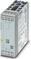
QUINT4-CAP/24DC/20/16KJ/USB - Capacity module
QUINT capacity module, with maintenance-free energy storage based on double-layer capacitor, DIN rail mounting, input: 24 V DC, output: 24 V DC / 20 A / 16 kJ incl. mounted UTA 107 universal DIN rail adapter
- Convenient shutdown of PCs
- Maintenance-free with a long service life
- Space savings, thanks to the compact design
- Long buffer time, thanks to high memory capacity
- Lockable USB interface for connecting to industrial PCs, for example
Technical Specifications
Input data
| Input Voltage | 24 V DC (SELV) |
| Input voltage range | 22.5 V DC ... 30 V DC |
| Fixed backup threshold | < 22 V DC |
| Fixed backup threshold | > 30 V DC |
| Current consumption IN (UN, IOUT = IN, Icharge = 0) | 20 A |
| Current consumption Imax (UN, IOUT = IStat.Boost, Icharge = max) | 30 A |
| Current consumption INo-Load(UN, IOUT = 0, Icharge = 0) | 0.1 A (No-load) |
| Current consumption Icharge (UN, IOUT = 0, Icharge = max) | 10 A (charging process) |
| Power consumption Pmax (UN, IOUT = IStat.Boost, Icharge = max) | 599 W |
| Power consumption PN (UN, IOUT = IN, Icharge = 0) | 488 W |
| Power consumption Pcharge (UN, IOUT = 0, Icharge = max) | 244 W |
| Buffer time | 4 min. (2.5 A) |
| Buffer time | 30 s (20 A) |
| Charging time | approx. 6.3 min. (2.5 A) |
| Charging time | approx. 2.1 min. (10 A) |
| Recharging time | approx. 5.4 min. (2.5 A) |
| Recharging time | approx. 1.4 min. (10 A) |
| Inrush Current | ≤ 7 A (≤ 4 ms) |
| Switch-on time | 1 ms (buffer mode) |
| Internal input fuse | no |
| Dielectric strength | max. 35 V DC (Reverse polarity protection) |
| Voltage drop, input/output | 0.5 V DC |
Output data
| Efficiency | > 98 % (with charged energy storage device) |
| Connection in parallel | yes |
| Connection in parallel | max. 4 |
| Connection in series | No |
Mains operation
| Output Voltage | 24 V DC |
| Output current IN | 20 A |
| Static Boost (IStat.Boost) | 25 A |
| Output power POUT (UN, IOUT = IN) | 480 W |
| Output power POUT (UN, IOUT = Istat.Boost) | 600 W |
| Power dissipation No load (UN, IOut = 0, ICharge = 0) | 3 W |
| Power dissipation Nominal load (UN, IOut = IN, ICharge = 0) | 10 W |
| Short-circuit-proof | yes (with input fuse) |
| Idling-proof | yes |
Battery operation
| Output Voltage | 24 V DC |
| Output current IN | 20 A |
| Static Boost (IStat.Boost) | 25 A |
| Output power POUT (UN, IOUT = IN) | 480 W |
| Output power POUT (UN, IOUT = Istat.Boost) | 600 W |
| Power dissipation No load (UN, IOut = 0, ICharge = 0) | 5 W |
| Short-circuit-proof | yes |
| Idling-proof | yes |
General
| Capacity | 16 kJ |
| Storage medium | Double-layer capacitor |
| Buffer time | 4 min. (2.5 A) |
| Buffer time | 30 s (20 A) |
Input
| Position | 1.x |
Connection technology
| Position marking | 1.1 (+), 1.2 (+), 1.3 (-), 1.4 (-) |
Conductor connection
| Connection Method | Screw connection |
| rigid | 0.2 mm² ... 6 mm² |
| flexible | 0.2 mm² ... 4 mm² |
| flexible with ferrule without plastic sleeve | 0.25 mm² ... 4 mm² |
| flexible with ferrule with plastic sleeve | 0.25 mm² ... 4 mm² |
| rigid (AWG) | 24 ... 10 |
| Stripping length | 8 mm |
| Tightening torque | 0.5 Nm ... 0.6 Nm |
| Drive form screw head | Slotted L |
2-conductor connection
| rigid | 0.2 mm² ... 1.5 mm² |
| flexible | 0.2 mm² ... 1.5 mm² |
| flexible with TWIN ferrule with plastic sleeve | 0.5 mm² ... 2.5 mm² |
Output
| Position | 2.x |
Connection technology
| Position marking | 2.1 (+), 2.2 (-) |
Conductor connection
| Connection Method | Screw connection |
| rigid | 0.2 mm² ... 6 mm² |
| flexible | 0.2 mm² ... 4 mm² |
| flexible with ferrule without plastic sleeve | 0.25 mm² ... 4 mm² |
| flexible with ferrule with plastic sleeve | 0.25 mm² ... 4 mm² |
| rigid (AWG) | 24 ... 10 |
| Stripping length | 8 mm |
| Tightening torque | 0.5 Nm ... 0.6 Nm |
| Drive form screw head | Slotted L |
2-conductor connection
| rigid | 0.2 mm² ... 1.5 mm² |
| flexible | 0.2 mm² ... 1.5 mm² |
| flexible with TWIN ferrule with plastic sleeve | 0.5 mm² ... 2.5 mm² |
Signal
| Position | 3.x |
Connection technology
| Position marking | 3.1 (13), 3.2 (14), 3.3 (Alarm), 3.4 (Ready), 3.5 (Remote), 3.6 (Parallel Port), 3.7 (SGnd) |
Conductor connection
| Connection Method | Push-in connection |
| rigid | 0.2 mm² ... 1 mm² |
| flexible | 0.2 mm² ... 1.5 mm² |
| flexible with ferrule without plastic sleeve | 0.2 mm² ... 1 mm² |
| flexible with ferrule with plastic sleeve | 0.2 mm² ... 0.75 mm² |
| rigid (AWG) | 24 ... 18 |
| Stripping length | 8 mm |
Interfaces
| Interface | USB (Modbus/RTU) |
| Number of interfaces | 1 |
| Connection Method | MINI-USB Type B |
| Position | 5.x |
| Locking | Screw |
| Transmission physics | USB 2.0 |
| Topology | Point-to-point |
| Transmission Speed | 9600 baud ... 115200 baud (Default: 115200 baud) |
| Transmission length | max. 5 m |
| Access time | ≤ 2 s |
| Chipset | Silicon Labs CP2104-F03-GM |
| Electrical isolation | Yes, UL approved |
Signal state Remote
| Connection labeling | 3.5 |
| Channel | DI (digital input) |
| State (configurable) | Remote |
| State condition | Remote |
| Low signal | <3 kΩ to SGnd |
| High signal | open (>470 k between Remote and SGnd) |
| Signal - state assignment | low - active |
| Reference potential | 3.7 (SGnd, identical to1.3, 1.4, 2.2) |
Signal state Parallel port
| Connection labeling | 3.6 |
| Channel | DI / DO (digital input / digital output) |
| Switching input description | Connection terminal block communication, parallel operation |
| State (configurable) | Parallel Mode |
| State condition (configurable) | Not active: noneActive:Output: buffer mode <1 VOutput: mains operation 24 V (UN-1 V (typical))Input: Connected with SGnd: start buffer mode |
| Switching voltage | < 1 V |
| Switching voltage | 24 V (UN - 1 V (typical)) |
| Current carrying capacity | 2 mA |
| Reference potential | Different device, parallel port IN/OUT |
Signal state Alarm
| Connection labeling | 3.3 |
| Channel | DO (digital output) |
| Switching output | Transistor |
| State (configurable) | Group alarm |
| State condition (configurable) | Alarm |
| Output Voltage | 24 V AC (UN - 1 V (typical)) |
| Output can be loaded | max. 20 mA |
| State - signal assignment | active - low |
| Reference potential | 3.7 (SGnd, identical to1.3, 1.4, 2.2) |
| LED status indicator | red (Alarm) |
Signal state UIN OK
| Connection labeling | 3.1, 3.2 |
| Channel | DO (digital output) |
| Switching output | Electronic relays (OptoMOS) |
| State (configurable) | UIn OK |
| State condition (configurable) | UIn > 22,5 V DC, UIn < 30 V DC |
| Output Voltage | max. 30 V |
| Output can be loaded | 300 mA |
| State - signal assignment | active - high |
| LED status indicator | green (UIn OK) |
Signal state Ready
| Connection labeling | 3.4 |
| Channel | DO (digital output) |
| Switching output | Transistor |
| State (configurable) | Ready |
| State condition (configurable) | State of charge = 100% or buffer mode |
| Output Voltage | 24 V (UN - 1 V (typical)) |
| Output can be loaded | max. 20 mA |
| State - signal assignment | active - high |
| Reference potential | 3.7 (SGnd, identical to1.3, 1.4, 2.2) |
| LED status indicator | Green (state of charge - SOC) |
Signal ground SGnd
| Connection labeling | 3.7 |
| Switching voltage | 0 V |
| Current carrying capacity | max. 60 mA |
| Function | Signal ground |
| Reference potential | 3.3 Alarm, 3.4 Ready, 3.5 Remote |
Electrical properties
| Insulation voltage input, output / housing | 500 V |
Product properties
| Product family | QUINT capacity module |
| MTBF (IEC 61709, SN 29500) | 1839057 h (25 °C) |
| MTBF (IEC 61709, SN 29500) | 1191809 h (40 °C) |
| MTBF (IEC 61709, SN 29500) | 597144 h (60 °C) |
Insulation characteristics
| Protection class | III (Special application (SELV)) |
| Overvoltage category | II |
| Degree of pollution | 2 |
Item dimensions
| Width | 244 mm |
| Height | 130 mm |
| Depth | 125 mm |
Installation dimensions
| Installation distance right/left | 0 mm / 0 mm |
| Installation distance top/bottom | 50 mm / 50 mm |
Mounting
| Mounting Type | DIN rail mounting |
| Assembly instructions | alignable: horizontally 0 mm, vertically 50 mm |
| Mounting Position | horizontal DIN rail NS 35, EN 60715 |
Material specifications
| Flammability rating according to UL 94 (housing / terminal blocks) | V0 |
| Housing Material | Metal |
Ambient conditions
| Degree of Protection | IP20 |
| Ambient Temperature (Operation) | -25 °C ... 60 °C (> 40 °C Derating: 1 %/K) |
| Ambient temperature (storage/transport) | -40 °C ... 60 °C |
| Ambient temperature (start-up type tested) | -40 °C |
| Maximum altitude | ≤ 4000 m |
| Climatic class | 3K3 (in acc. with EN 60721) |
| Max. permissible relative humidity (operation) | ≤ 95 % |
| Shock | 30g, 18 ms per spatial direction (in accordance with IEC 60068-2-27) |
| Vibration (Operation) | 0,7g |
Overvoltage category
| EN 61010-1 | II (≤ 4000 m) |
| EN 61010-2-201 | II (≤ 4000 m) |
| UL 60950-1 | II (≤ 4000 m) |
Protective extra-low voltage
| Standard designation | Protective extra-low voltage |
| Standards/specifications | IEC 61010-1 (SELV) |
| Standards/specifications | IEC 61010-2-201 (PELV) |
UL
| Identification | UL 61010-1 |
| Identification | UL 61010-2-201 |
| Identification | UL 121201 |
| Identification | CAN/CSA-C22.2 No. 61010-1-12 |
| Identification | CAN/CSA C22.2 No. 61010-2-201:14 |
| Identification | CSA C22.2 No. 213-17 Class I, Devsion 2, Groups A, B, C, D (Hazardous Location) |
CB scheme
| Identification | IEC 61010-1 |
| Identification | IEC 61010-2-201 |
| Identification | EN 61010-1 |
| Identification | EN 61010-2-201 |
EMC data
| Interference emission | Noise emission in accordance with EN 61000-6-3 and EN 61000-6-4 |
| Noise immunity | Device immunity in accordance with EN 61000-6-2 |
| Electromagnetic compatibility | Conformance with EMC Directive 2014/30/EU |
| Noise emission | EN 55016 |
| Noise emission | EN 61000-6-3 |
Electrostatic discharge
| Standards/regulations | EN 61000-4-2 |
| Contact discharge | 6 kV (Test Level 3) |
| Discharge in air | 8 kV (Test Level 3) |
| Comments | Criterion B |
Electromagnetic HF field
| Standards/regulations | EN 61000-4-3 |
| Frequency Range | 80 MHz ... 6 GHz |
| Test field strength | 10 V/m |
| Comments | Criterion A |
Fast transients (burst)
| Standards/regulations | EN 61000-4-4 |
| Input | 2 kV (Test Level 3 - asymmetrical) |
| Output | 2 kV (Test Level 3 - asymmetrical) |
| Signal | 2 kV (Test Level 3 - asymmetrical) |
| Comments | Criterion A |
Surge voltage load (surge)
| Standards/regulations | EN 61000-4-5 |
| Signal | 1 kV (Test Level 2 - asymmetrical) |
| Comments | Criterion B |
| Input/Output | 1 kV (Test Level 2 - symmetrical) |
| Input/Output | 2 kV (Test Level 3 - asymmetrical) |
Conducted interference
| Standards/regulations | EN 61000-4-6 |
| Frequency Range | 0.15 MHz ... 80 MHz |
| Comments | Criterion A |
| Voltage | 10 V |
Criteria
| Criterion A | Normal operating behavior within the specified limits. |
| Criterion B | Temporary impairment to operational behavior that is corrected by the device itself. |
Why Proax for Phoenix Contact 1065635?
Proax is an authorized distributor of Phoenix Contact 1065635 and one of Phoenix Contact's largest distributors in North America. Our highly skilled in-house technical team is ready to assist with any technical needs.
Have a question in mind? to help you get the right product as quickly as possible for your project. We're always here to help!
Short Lead Time
Highly Trained Staff
Live Chat
Technical Support
Local Inventory
60+ Years Experience
Additional Information
| Pack Size | 1 |
Recommended

 QUINT capacity module, with maintenance-free energy storage based on double-layer capacitor, DIN rail mounting, input: 24 V DC, output: 24 V DC / 20 A / 16 kJ incl. mounted UTA 107 universal DIN rail adapter
 QUINT capacity module, with maintenance-free energy storage based on double-layer capacitor, DIN rail mounting, input: 24 V DC, output: 24 V DC / 20 A / 16 kJ incl. mounted UTA 107 universal DIN rail adapter
 QUINT capacity module, with maintenance-free energy storage based on double-layer capacitor, DIN rail mounting, input: 24 V DC, output: 24 V DC / 20 A / 16 kJ incl. mounted UTA 107 universal DIN rail adapter
 QUINT4-CAP/24DC/10/8KJ - QUINT capacity module, with maintenance-free energy storage based on double-layer capacitor, DIN rail mounting, input: 24 V DC, output: 24 V DC / 10 A / 8 kJ incl. mounted UTA 107 universal DIN rail adapter. The “POWER MANAGEMENT SUITE” software (Item No. 1252232) available in the download area can be used for configuration.
 QUINT4-CAP/24DC/3.8/1KJ/PT - QUINT capacity module with maintenance-free double-layer capacitor-based energy storage for DIN rail mounting, input: 24 V DC, output: 24 V DC / 3.8 A / 1 kJ
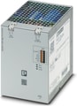 QUINT4-CAP/24DC/5/4KJ - QUINT capacity module, with maintenance-free energy storage based on double-layer capacitor, DIN rail mounting, input: 24 V DC, output: 24 V DC / 5 A / 4 kJ incl. mounted UTA 107 universal DIN rail adapter. The “POWER MANAGEMENT SUITE” software (Item No. 1252232) available in the download area can be used for configuration.
 QUINT4-CHARGER/1AC/24DC/10 - Battery charger QUINT CHARGER, Screw connection, DIN rail mounting, input: 1-phase, output: 24 V DC / 10 A
 QUINT4-BUFFER/24DC/20 - QUINT buffer module with maintenance-free capacitor-based energy storage for DIN rail mounting, input: 24 V DC, output: 24 V DC/20 A, including mounted UTA 107 universal DIN rail adapter.
 QUINT4-BUFFER/24DC/40 - QUINT buffer module with maintenance-free capacitor-based energy storage for DIN rail mounting, input: 24 V DC, output: 24 V DC/40 A, including mounted UTA 107 universal DIN rail adapter.
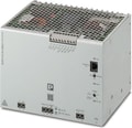 QUINT4-INV/24DC/1AC/600VA/USB - QUINT INVERTER, DIN rail mounting, input:24 V DC, output:1AC / 600 VA, Pure sine.
 Active redundancy module QUINT ORING with decoupling MOSFET, ACB Technology, DIN rail mounting, 12 V DC ... 24 V DC, 2x 10 A, 2x 10 A
 Active redundancy module QUINT ORING with decoupling MOSFET, ACB Technology, DIN rail mounting, 12 V DC ... 24 V DC, 2x 20 A, 2x 20 A
 QUINT4-PS/12-24DC/24DC/1.3/PT - Primary-switched DC/DC converter, QUINT POWER, DIN rail mounting, input: 12 V DC - 24 V DC, output: 24 V DC / 1.3 A
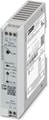 QUINT4-PS/12-24DC/24DC/1.3/SC - Primary-switched DC/DC converter, QUINT POWER, DIN rail mounting, input: 12 V DC - 24 V DC, output: 24 V DC / 1.3 A
 QUINT4-PS/12-24DC/24DC/2.5/PT - Primary-switched DC/DC converter, QUINT POWER, DIN rail mounting, input: 12 V DC - 24 V DC, output: 24 V DC / 2.5 A
 QUINT4-PS/12-24DC/24DC/2.5/SC - Primary-switched DC/DC converter, QUINT POWER, DIN rail mounting, input: 12 V DC - 24 V DC, output: 24 V DC / 2.5 A
 QUINT4-PS/12-24DC/5-15DC/2.5/PT - Primary-switched DC/DC converter, QUINT POWER, DIN rail mounting, input: 12 V DC - 24 V DC, output: 12 V DC / 2.5 A
 QUINT4-PS/12DC/24DC/5/PT - Primary-switched DC/DC converter, QUINT POWER, DIN rail mounting, SFB Technology (Selective Fuse Breaking), input: 12 V DC, output: 24 V DC / 5 A